Front axle versions
Section F01 of the catalogue covers several front axle builds. Steer drive axles 2WS/4WD: 448/42400 (35 km/h; it replaces the discontinued 448/55000, frames F1-1), 448/57390 with a 19.2:1 ratio for 20" front tyres (F1-4), 448/57400 at 30 km/h and 16.2:1 (F1-5), 448/57470 and 448/57480 at 15.785:1 (F1-6; 448/57480 is superseded by 448/57570), 448/57510 at 15.78:1 (F1-7), 448/58220 at 15.78:1 (F1-17, superseded by 448/57510), 448/57990 at 14.123:1 (F1-51) and the black 448/58190 axle of the 60th Anniversary edition at 16.2:1 (F1-60, superseded by 448/57400). Machines with rear-wheel drive only use the non-driven 2WS/2WD axle 128/12482 (frame F1-10; it replaces 128/12601), which has a stub axle on a kingpin instead of a steering hub with a drive shaft.
The drive heads differ as well: the catalogue lists crown wheel and pinion sets with 9/32, 11/33, 13/34 and 13/38 teeth. Axle 448/57510 has a 2.923:1 drive head (13/38 set). Parts are therefore selected by the axle number on its data plate and the machine serial number, and gears are checked by their tooth count. Axle design is described in our article on JCB 3CX / 4CX transmission.
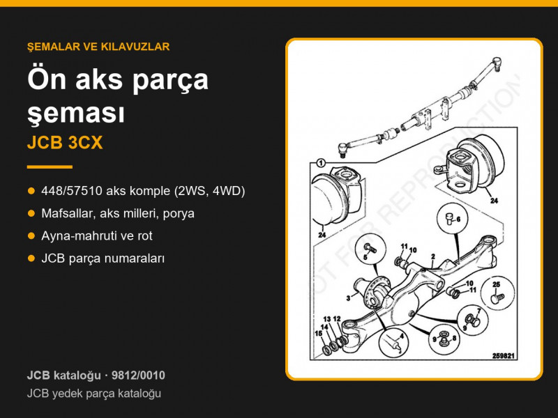
Front axle 448/57510 assembly
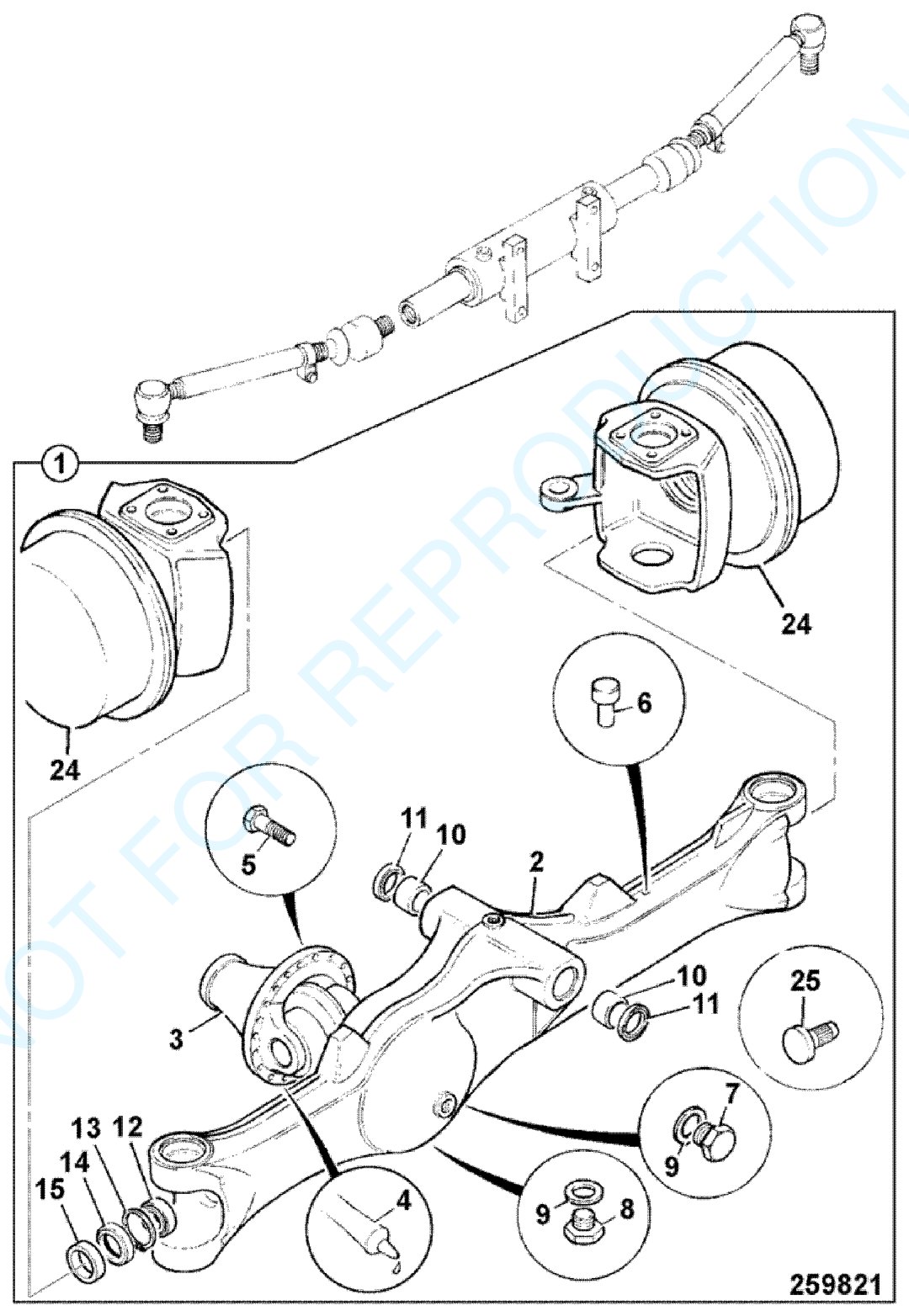
JCB 3CX front axle 448/57510, 2WS, 4WD, 15.78:1 (JCB parts catalogue, frame F1-7-1). Click the image to view it full size.
| Item | JCB part no. | Part | Qty |
|---|---|---|---|
| 1 | 448/57510 | Front axle assembly, steer drive, 4WD, 15.78:1 | 1 |
| 2 | 458/20744 | Axle casing SD55 (replaces 458/20554) | 1 |
| 3 | — | Drive head with differential, see frame F1-7-30 | 1 |
| 4 | 4102/1204 | JCB Multi-Gasket sealant | as required |
| 5 | 826/01434 | Bolt, Verbus Ripp M10×35 | 12 |
| 6 | 448/56282 | Breather, spring type, M10×1.5 thread | 1 |
| 7 | 816/80037 | Filler plug, 33 mm hex | 1 |
| 8 | 816/80012 | Magnetic drain plug, 3/4" BSP, 33 mm hex | 1 |
| 9 | 1406/0021 | Sealing washer | 2 |
| 10 | 829/00548 | Bush | 2 |
| 11 | 904/06500 | Oil seal | 2 |
| 12 | 907/08400 | Bearing | 2 |
| 13 | 2203/1082 | Circlip | 2 |
| 14 | 904/50040 | Oil seal | 2 |
| 24 | — | Hub assemblies, see frames F1-7-10 and F1-7-20 | 2 |
| 25A | 123/07719 | Lock stop, Ø28.5 mm, 15 mm head (20" wheels) | 2 |
| 25B | 1315/0712Z | Bolt M16×50 (20" wheels) | 2 |
| 25C | 829/30821 | Spacer (20" wheels) | 2 |
The axle is built around the SD55 casing (item 2), to which the drive head (item 3) is fitted on sealant and secured with bolts (item 5). The casing eyes for the axle pivot carry bushes (item 10) and oil seals (item 11), while the casing ends hold the drive shaft bearings (item 12), circlips (item 13) and oil seals (item 14). The oil level is checked at the filler plug (item 7) and the oil is drained through the magnetic plug (item 8); the spring-type breather (item 6) equalises the pressure inside the axle. The lock stop, bolt and spacer (items 25A–25C) are used on machines with 20" wheels.
Steering hubs, kingpins and drive shafts
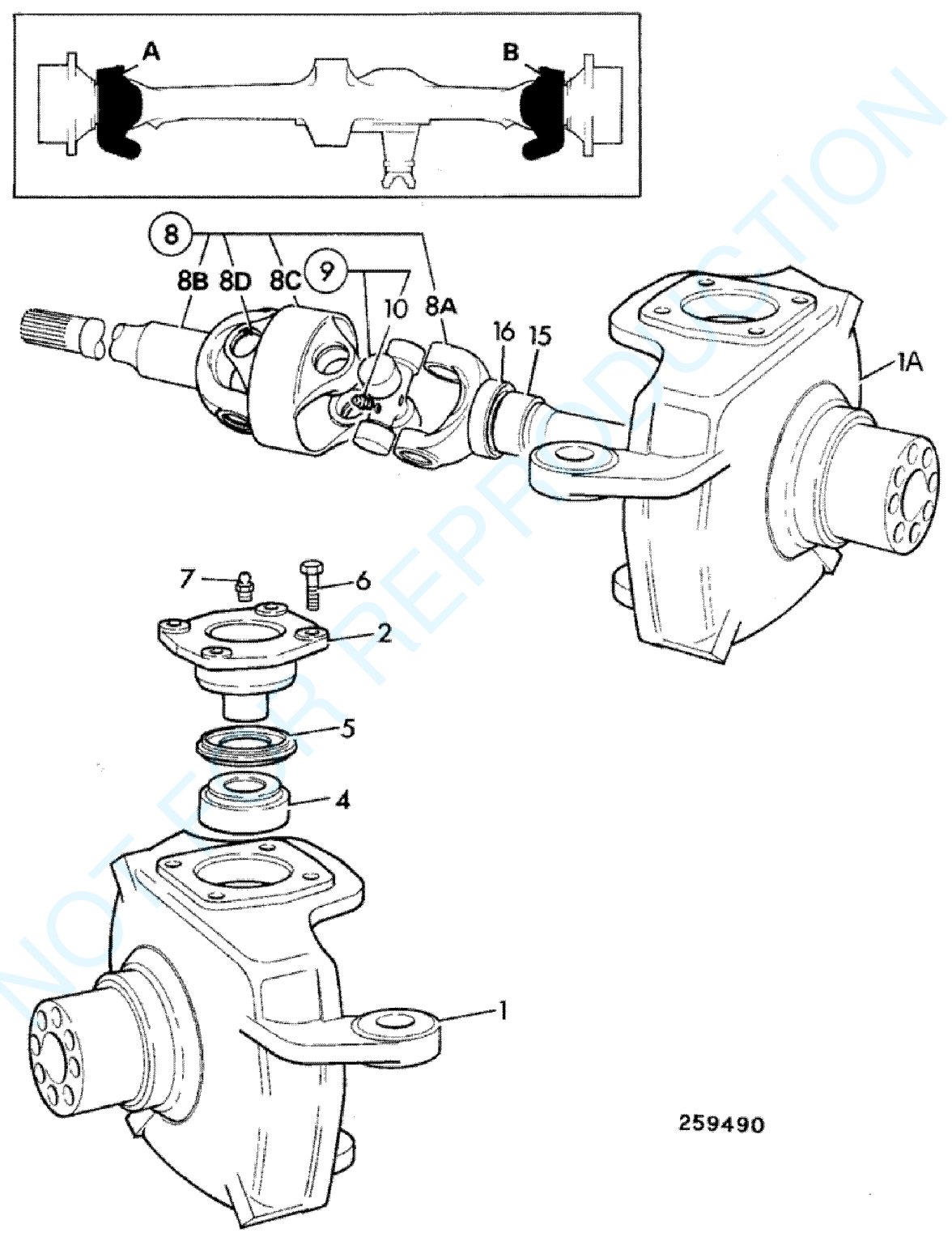
Steering hub and drive shaft, front axle 448/57510 (JCB parts catalogue, frame F1-7-10). Click the image to view it full size.
| Item | JCB part no. | Part | Qty |
|---|---|---|---|
| 1 | 458/20404 | Steering hub with lock stop, side A | 1 |
| 1A | 458/20405 | Steering hub with lock stop, side B | 1 |
| 2 | 448/42402 | Kingpin (pivot pin) | 4 |
| 4 | 907/08300 | Taper roller bearing | 4 |
| 5 | 904/06700 | Oil seal | 4 |
| 6 | 1321/0509 | Screw | 16 |
| 7 | 816/60056 | Grease nipple, self-tapping | 4 |
| 8 | 914/86200 | Drive shaft assembly, 1275 mm long (side A) | 1 |
| 8 | 914/86300 | Drive shaft assembly, 825 mm long (side B) | 1 |
| 8A | 914/86201 | Shaft, hub end (A and B) | 1 |
| 8B | 914/86204 | Shaft, axle end, 960.5 mm (side A) | 1 |
| 8B | 914/86301 | Shaft, axle end, 511.5 mm (side B) | 1 |
| 8C | 914/86203 | Centre spacer (A and B) | 1 |
| 8D | 914/83303 | Circlip (A and B) | 1 |
| 9 | 914/86202 | Universal joint kit (A and B) | 2 |
| 15 | 917/50200 | Bearing | 2 |
| 16 | 904/50047 | Oil seal | 2 |
Each steering hub (items 1, 1A) swivels on two kingpins (item 2), upper and lower, each fitted with a taper roller bearing (item 4) and an oil seal (item 5); the joints are greased through the grease nipples (item 7). Drive reaches the wheel through a shaft with a double universal joint: the axle-end shaft (item 8B), the centre spacer (item 8C) with two UJ crosses (item 9) and the hub-end shaft (item 8A). The side A and side B shafts differ in length — 1275 and 825 mm as assemblies — so always state the side when ordering. The shaft runs in a bearing (item 15) sealed by an oil seal (item 16).
Hub and planetary hub reduction

Hub and hub reduction, front axle 448/57510 (JCB parts catalogue, frame F1-7-20). Click the image to view it full size.
| Item | JCB part no. | Part | Qty |
|---|---|---|---|
| 1 | 450/10216 | Planet carrier, 5-stud (formerly 450/12401) | 2 |
| 2 | 826/00425 | Taper plug 3/4"-14PTF | 2 |
| 3 | 450/10208 | Thrust washer | 2 |
| 4 | 821/00216 | External circlip | 2 |
| 5 | 828/00196 | O-ring | 2 |
| 6 | 450/12403 | Sun gear | 2 |
| 7 | 821/00209 | Circlip | 12 |
| 8 | 907/50200 | Double row roller bearing | 6 |
| 9 | 450/10206 | Planet gear | 6 |
| 10 | 2203/0054 | Circlip | 6 |
| 11 | 921/50000 | Spacer, 32 mm long | 2 |
| 12 | 450/10205 | Annulus (ring gear) | 2 |
| 13 | 450/12702 | Annulus carrier | 1 |
| 14 | 826/01060 | Bolt M14×70 | 16 |
| 15 | 821/00210 | Internal circlip, square section | 2 |
| 16 | 907/M7473 | Bearing | 4 |
| 17 | 450/12703 | Hollow dowel | 16 |
| 18 | 450/10221 | Wheel hub, 5-stud (without studs) | 2 |
| 19 | 826/00923 | Wheel stud | 10 |
| 20 | 904/50033 | Cassette seal | 2 |
| 20 | 458/20403 | Hub seal cover | 1 |
| 22 | 1321/0407Z | Bolt M10×25, plated | 4 |
Each hub contains a planetary reduction: the sun gear (item 6) on the drive shaft turns three planet gears (item 9) running on double row roller bearings (item 8); the planet gears roll around the annulus (item 12) and drive the planet carrier (item 1) together with the wheel hub (item 18). The annulus is mounted on its carrier (item 13), which is secured with M14×70 bolts (item 14) and hollow dowels (item 17). The hub turns on bearings (item 16) and is sealed by a cassette seal (item 20). Oil is filled and drained through the 3/4"-14PTF taper plug (item 2). Quantities in the table are per axle, i.e. for both hubs.
Crown wheel and pinion, differential
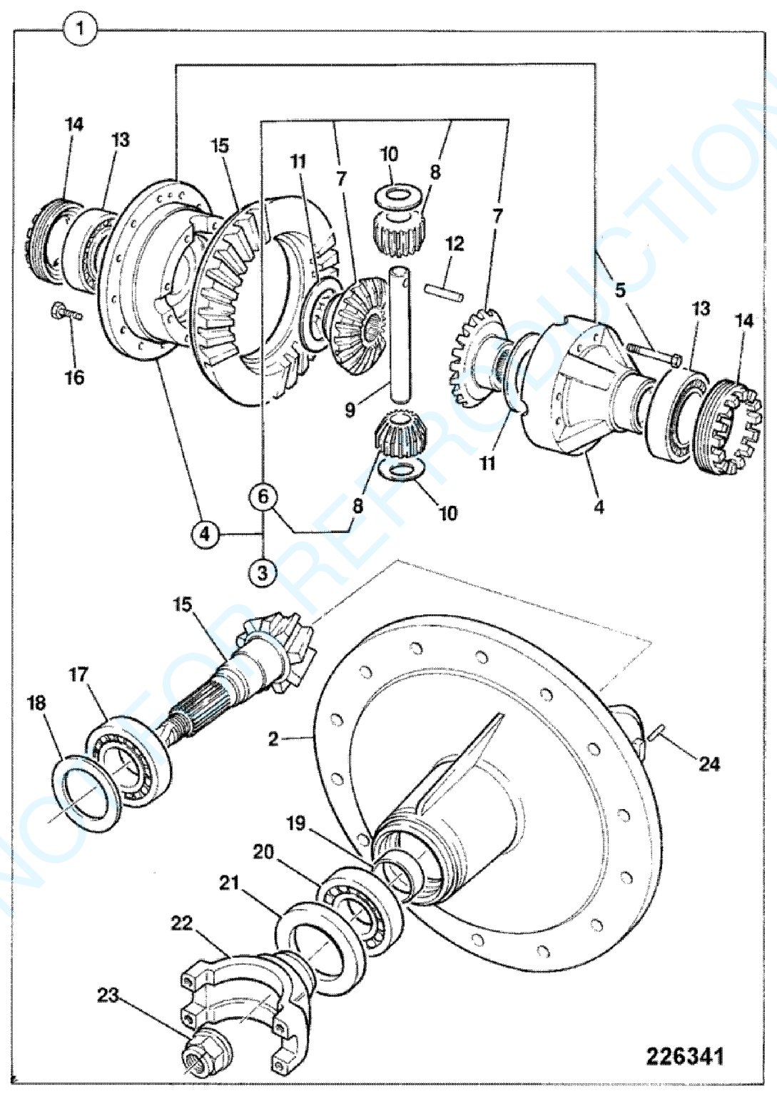
Crown wheel and pinion with differential, front axle 448/57510 (JCB parts catalogue, frame F1-7-30). Click the image to view it full size.
| Item | JCB part no. | Part | Qty |
|---|---|---|---|
| 1 | 458/10600 | Drive head with differential, 2.923:1 (up to axle 448/57510/7) | 1 |
| 1 | 458/M1873 | Drive head assembly (from axle 448/57510/8) | 1 |
| 2 | 448/15701 | Drive head housing | 1 |
| 4 | 448/23500 | Differential case | 1 |
| 5 | 826/01585 | Bolt | 8 |
| 6 | 448/36400 | Differential gear kit | 1 |
| 9 | 448/05408 | Cross shaft | 1 |
| 10 | 808/00210 | Thrust washer, planet gear | 2 |
| 11 | 808/00209 | Thrust washer, side gear | 2 |
| 12 | 2102/0816 | Roll pin | 1 |
| 13 | 907/09200 | Taper roller bearing | 2 |
| 14 | 448/05405 | Differential adjusting nut | 2 |
| 15 | 458/70189 | Crown wheel and pinion 38/13 (version A, no longer available, see TI GEN232) | 1 |
| 15 | 458/M1350 | Crown wheel and pinion 13/38 (version B) | 1 |
| 16 | 826/01084 | Bolt | 12 |
| 17 | 907/09000 | Roller bearing | 1 |
| 18 | 921/01900 | Shim kit | as required |
| 19 | 921/53300 | Spacer kit | 1 |
| 20 | 907/09100 | Taper roller bearing | 1 |
| 21 | 904/50023 | Pinion seal, triple lip, shaft 55.0/54.81 mm | 1 |
| 22 | 450/27200 | Flange (version A) | 1 |
| 22 | 458/20813 | Yoke flange (version B) | 1 |
| 23 | 826/01483 | Nut M24 with washer, staking type (version A) | 1 |
| 23 | 826/01744 | Nut M30, staking type (version B) | 1 |
| 24 | 826/00818 | Roll pin | 2 |
The drive head was produced in two versions: A — 458/10600 for axles up to 448/57510/7, and B — 458/M1873 for axles from 448/57510/8 onwards. They differ in the crown wheel and pinion (item 15), the flange (item 22) and the pinion nut (item 23): M24 with washer on version A, M30 on version B. Crown wheel and pinion mesh is set with shims (item 18) and spacers (item 19); differential bearing (item 13) preload is set with the adjusting nuts (item 14), which are locked by roll pins (item 24). The differential assembly and the individual gears (items 3, 7, 8) appear in the catalogue without part numbers as non-serviceable items, so the differential gears are ordered as kit 448/36400.
Track rod
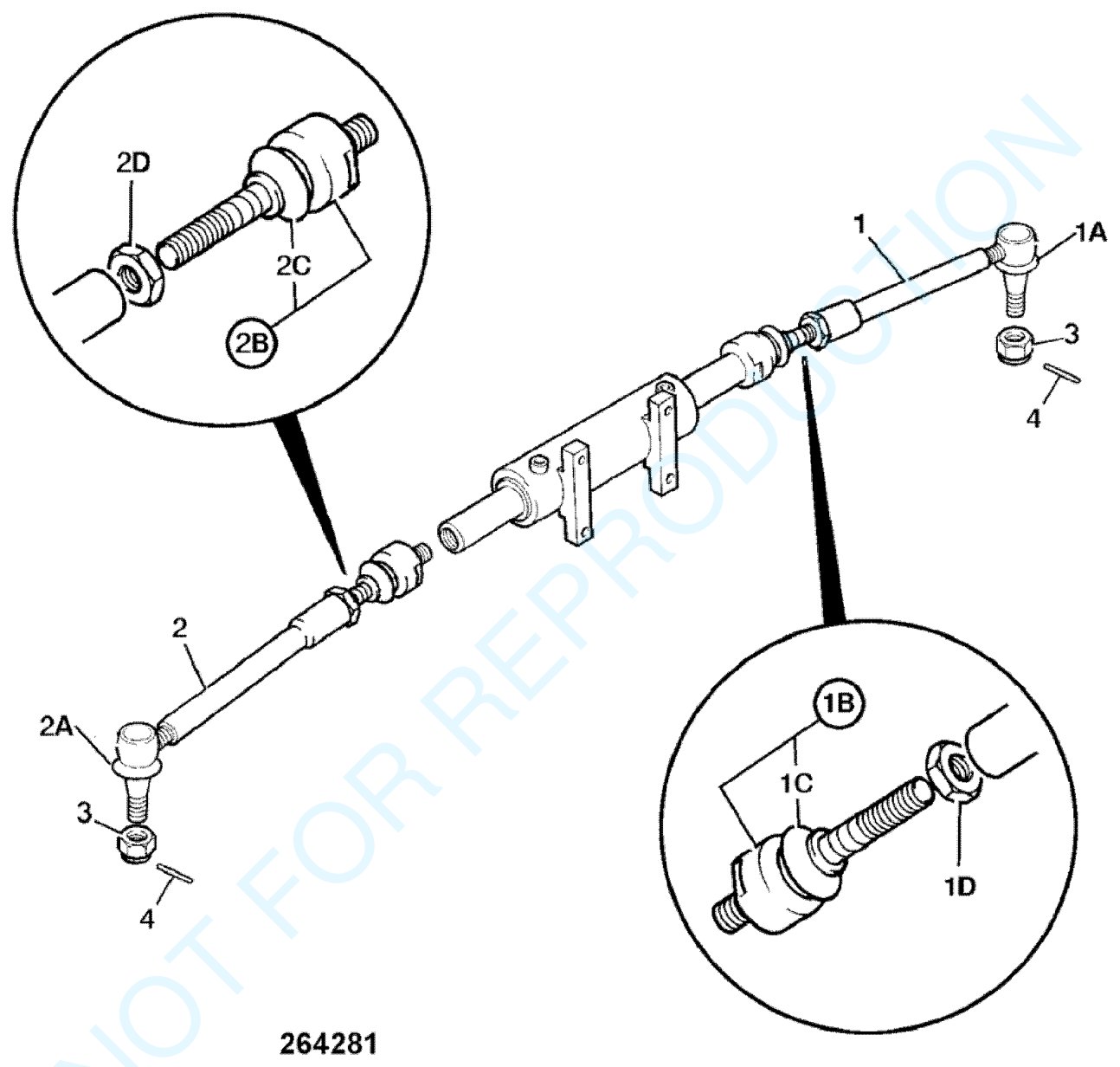
Track rod with steering ram, 2WS 4WD front axle (JCB parts catalogue, frame F1-30-10). Click the image to view it full size.
| Item | JCB part no. | Part | Qty |
|---|---|---|---|
| 1, 2 | 126/02253 | Track rod M24/M22 | 2 |
| 1A, 2A | 123/07855 | Dust boot, outer track rod end | 2 |
| 1B, 2B | 331/14861 | Ball joint, cylinder end | 2 |
| 1C, 2C | 123/07689 | Ball joint dust boot | 2 |
| 1D, 2D | 458/80026 | Locknut | 2 |
| 3 | 826/01372 | Castellated nut M20×1.5 | 2 |
| 4 | 2103/1112 | Split pin | 2 |
The steering ram is mounted on the axle, and its rod is connected through ball joints (items 1B, 2B) to two M24/M22 track rods (items 1, 2). The outer track rod ends are fixed to the steering hub arms with M20×1.5 castellated nuts (item 3) and split pins (item 4). The joints are protected by dust boots (items 1A, 1C, 2A, 2C), and the joint on each rod is held by a locknut (items 1D, 2D). Steering checks and adjustment are covered in our article on JCB 3CX / 4CX steering.
Axle pivot pin, lubrication and lock stops

Front axle pivot pin and grease line (JCB parts catalogue, frame F1-3-1). Click the image to view it full size.
| Item | JCB part no. | Part | Qty |
|---|---|---|---|
| 1 | 811/10091 | Axle pivot pin | 1 |
| 2 | 819/00132 | Spacer, grey, 50.75 mm bore, 3.5 mm thick | 1 |
| 2 | 819/00133 | Spacer, cream, 50.75 mm, 4.0 mm thick | 1 |
| 2 | 819/00134 | Spacer, yellow, 50.75 mm, 4.5 mm thick | 1 |
| 2 | 819/00135 | Spacer, blue, 50.75 mm, 5.0 mm thick | 1 |
| 2 | 819/00136 | Spacer, red, 50.75 mm, 5.5 mm thick | 1 |
| 2 | 819/00137 | Spacer, black, 50.75 mm, 6.0 mm thick | 1 |
| 3 | 1315/3520Z | Bolt M12×100 | 1 |
| 4 | 1370/0403Z | Self-locking nut M12 | 1 |
| 7 | 1609/0001 | Adaptor | 1 |
| 8 | 649/52077 | Hose 1/8" BSP, 490 mm long (formerly 649/50023, 649/41900) | 1 |
| 9 | 826/00871 | Nut | 1 |
| 10 | 816/20070 | Adaptor for 16.3 mm hole in chassis (up to March 2005) | 1 |
| 10 | 816/20049 | Adaptor for 10.5 mm hole in chassis | 1 |
| 11 | 1450/1007 | Grease nipple | 1 |
| 12 | 835/00017 | Grease nipple cap | 1 |
| 15 | 123/06223 | Bonded washer | 1 |
The front axle oscillates relative to the chassis on the pivot pin (item 1), which is retained by an M12×100 bolt (item 3) and a self-locking nut (item 4). Play is taken up with spacers (item 2) with a 50.75 mm bore — six thicknesses from 3.5 to 6.0 mm in 0.5 mm steps, each in its own colour. Grease reaches the pin through a hose (item 8) from a remote grease nipple (item 11); the adaptor (item 10) is chosen to suit the hole in the chassis — 16.3 or 10.5 mm. This frame applies to 2WS axles with both 2WD and 4WD.
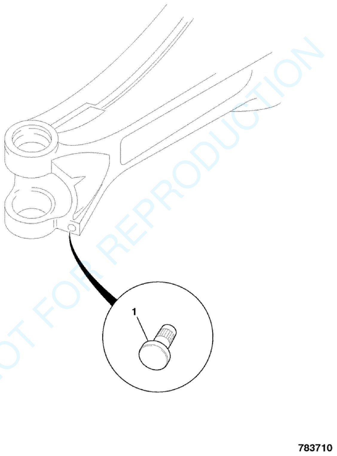
Steering lock stop on the front axle casing (JCB parts catalogue, frame F1-1-0). Click the image to view it full size.
The steering angle of the wheels is limited by lock stops next to the kingpin bosses on the axle casing. Their length depends on the wheel and tyre size:
| Item | JCB part no. | Part | Qty |
|---|---|---|---|
| F1-1-0, item 1 | 123/00625 | Lock stop, 8 mm — AWS machines with 28" wheels | 4 |
| F1-1-0, item 2 | 123/06738 | Lock stop, 35 mm long — 2WS front axles with 335/80×18 tyres | 2 |
| F1-1-1, item 25 | 123/07719 | Lock stop, Ø28.5 mm, 15 mm head — 12" rims | 2 |
| F1-1-1, item 25 | 123/06738 | Lock stop, 35 mm long — 18" rims | 2 |
| F1-1-1, item 25 | 123/06718 | Lock stop, 45 mm long — 20" rims | 2 |
Parts can be found in the front axle, reduction gears, half shafts, propshafts and UJs, bearings and seals and oil seals categories. Drawings for the PD70 rear axle are in our article on the JCB 3CX rear axle parts breakdown. To choose a part, send us the axle number from its data plate and the machine serial number.
Parts enquiries