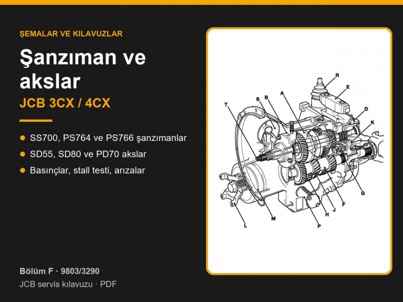
Below are the contents by page and a summary of the most useful data: which gearboxes and axles are fitted to the machines, gear ratios and gearbox pressures. Page numbers follow the manual (F-23, F-150 and so on).
Contents by page — JCB 3CX / 4CX transmission
| Pages | What the section covers |
|---|---|
| F-1 – F-8 | Service tools: axle and gearbox tools, adapters for pressure and flow testing |
| F-9 – F-42 | Technical data: tyres and tyre pressures, front and rear axles, SS700, PS764, PS766 gearboxes, stall speeds for SA, SB, SD and SF type engines |
| F-43 – F-90 | Description and operation: SD55 and SD80 axles, Synchro Shuttle and Powershift gearboxes — hydraulics, forward and reverse clutches, 4WD clutch, synchromesh |
| F-91 – F-145 | Electrical connections: Synchro Shuttle, Powershift, Powershift ShiftMaster with control unit, lock-up torque converter |
| F-146 – F-248 | Service procedures: renewing the axle pinion oil seal, gearbox flushing, stall test, pressure and flow tests, clutch leakage, solenoid valves, pressure and temperature sensors |
| F-249 – F-275 | Fault finding: Powershift gearbox (with a test record sheet) and Synchro Shuttle gearbox |
| F-276 – F-299 | Removal, dismantling and assembly: propshafts, non-driven front axle, SD55, SD80 and PD70 axles, gearboxes, torque converter |
| F-300 onwards | Oil cooler: removal and replacement |
Which gearbox is fitted to the JCB 3CX and 4CX
Three types of gearbox were fitted. The Synchro Shuttle SS700 is a manual synchromesh gearbox with electro-hydraulic direction selection; the manual mentions two SS700 versions — with a layshaft access cover and with an enclosed layshaft (type 2, page F-22). The Powershift PS764 and PS766 are fully electro-hydraulic, with an oil-immersed park brake built into the gearbox (pages F-26, F-29). All gearboxes work with a 310 mm torque converter.
| Gearbox | Gears | Forward ratios | Weight (dry) |
|---|---|---|---|
| SS700, standard ratios | 4, manual shift | 5.56; 3.45; 1.83; 1.00 | 170 kg (2WD), 200 kg (4WD) |
| SS700, low ratios | 4, manual shift | 6.56; 4.06; 1.90; 1.00 | 170 kg (2WD), 200 kg (4WD) |
| PS764 | 4 forward, 4 reverse | 7.97; 4.29; 1.86; 1.00 | 242 kg (4WD) |
| PS766 | 6 forward, 4 reverse | 8.17; 4.90; 3.62; 2.25; 1.35; 1.00 | not given in the manual |
Torque converters 04/600784 and 04/600786 give a torque multiplication at stall of 2.52 and 3.01, and the lock-up converter 04/600785 gives 2.52 (pages F-23, F-26). Gearbox parts, clutches and seals are in the transmission and gearbox parts category, and shift solenoid valves in solenoids and valves.
Which axles are fitted to the JCB 3CX and 4CX
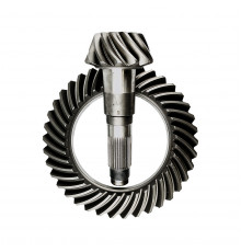
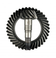
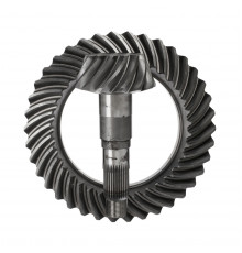
All driven axles are JCB units with spiral bevel crown wheel and pinion and epicyclic hub reduction with a 5.4 ratio (pages F-13 – F-21). The axle type depends on the machine build: four wheel steer (4WS), two wheel steer with four wheel drive, or rear wheel drive only.
| Axle | Position | Overall ratio | Notes |
|---|---|---|---|
| SD80, one-piece | front, 4WS machines | 18.16 | crown wheel and pinion 37/11 teeth, approx. 385 kg |
| SD55, one-piece | front, four wheel drive with two wheel steer | 16.2; 19.2; 14.123 or 15.78 | four crown wheel and pinion options, approx. 330 kg |
| Non-driven | front, rear wheel drive only | — | 3° camber, approx. 239 kg |
| SD80, three-piece | rear, 4WS machines | 15.78; 18.16 or 13.7 | inboard brakes, 5 friction and 6 steel plates per half shaft |
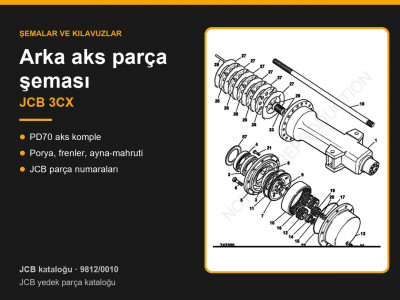
| PD70, three-piece | rear, two wheel steer machines | 15.78; 18.16 or 13.7 | inboard brakes, approx. 386 kg |
The manual stresses that the axle ratio must match the gearbox, and a replacement axle with a different ratio must not be fitted. When ordering parts, quote the details from the axle data plate, and when renewing gears check the number stamped on the gear and the number of teeth. On the rear axles of Synchro Shuttle machines the park brake disc is mounted on the pinion. Axle parts are in the front axle, rear axle and hub reductions and gear units categories, propshafts and universal joints in half shafts, propshafts, universal joints.
JCB gearbox pressures: specifications
Pressures are checked in neutral with the oil at working temperature. The table gives values at an oil temperature of 50 °C (pages F-23 – F-30); figures at 100 °C, converter out pressure and cooler flow are given on the same pages.
| Item, bar | SS700 | PS764 | PS766 |
|---|---|---|---|
| Main line, 1000 rev/min | 11.0–13.0 | 11.0–13.0 | 11.4–15.7 |
| Main line, 2000 rev/min | 13.0–15.6 | 13.0–15.2 | 12.4–17.0 |
| Converter in, 2000 rev/min | 5.3–6.7 | 5.8–6.9 | 4.0–6.8 |
| Lubrication, 2000 rev/min | 1.8–2.4 | 1.1–2.1 | 0.5–1.0 |
The pressure at each clutch must be within 0.7 bar of main line pressure, and within 1.4 bar for the PS764 4WD clutch. Gearbox pump flow at 2000 rev/min is 24–33 l/min for the SS700 (oil at 50 °C) and the PS764 (the manual gives this figure at 100 °C), and at least 34 l/min for the PS766. Carry out the tests strictly in the order given (page F-151 for SS700, F-160 for Powershift): low flow points to a worn pump or a blocked suction strainer, while high pressure with low flow points to a blocked oil cooler. During the clutch leakage test, flow must not drop by more than 4.5 l/min when a drive is engaged.
Torque converter stall test
The stall test shows the condition of the gearbox and engine from the engine speed at which the torque converter stops transmitting torque (page F-150 for SS700, F-158 for Powershift). Tables of normal stall speeds for the various engine and gearbox combinations are on pages F-31 – F-42.
- Warm the engine and gearbox to working temperature (oil above 50 °C) and check the maximum no-load engine speed.
- Apply the park brake and the service brakes. With the park brake applied the drive is disengaged electrically, so move the lever forward just until the warning light goes out and hold it there throughout the test.
- Select a gear, open the throttle fully and note the engine speed, then repeat in reverse. Do not stall the converter for longer than 10 seconds or the oil will overheat.
- A stall speed above normal indicates clutch slip or internal leakage in the gearbox. Below normal means the engine is not developing full power or the converter reaction member clutch is slipping.
- On Powershift gearboxes remove the dipstick before the test: if smoke comes from the dipstick tube, stop the test at once and strip the gearbox.
Gearbox flushing and axle service
If water has got into the gearbox oil or the wrong oil has been used, the gearbox is flushed (pages F-149, F-157): drain the oil, clean the suction strainer, renew the oil filter, fill with JCB Special Transmission Fluid and warm it to 50–100 °C. Then, for half an hour, stall the converter for 5 seconds after every 5 minutes of running; once the oil has cooled, drain and inspect it. If it is still contaminated, repeat the flush. Transmission oils are listed in the transmission oil category.
The front axle pinion oil seal can be renewed without removing the axle (page F-146). Measure the axle rolling torque before dismantling; after fitting the new seal, tighten the nut until the rolling torque has increased by 0.5–1 Nm. The maximum nut torque is 300 Nm. If at least 250 Nm cannot be reached, or the rolling torque rises by more than 1 Nm, rebuild the pinion assembly with a solid spacer. The procedure for the rear axle is the same (page F-148). Always support a raised machine on safe stands: never work under a machine held only by hydraulic rams or jacks.
Powershift gearbox faults: the manual’s fault finding tables
The Powershift fault finding tables start on page F-249 and work from simple checks to more involved ones: machine drives but lacks power in all gears (page F-251), will not drive in any gear (F-253), some gears will not engage (F-254), gearbox overheating (F-255), noise (F-256), 4WD or reverse will not engage (F-257 – F-260), water in the gearbox oil. The Synchro Shuttle tables are on page F-265. Test results can be recorded on the sheet on page F-250. To choose parts, send us the machine model and serial number, gearbox type and the details from the gearbox or axle data plate.
Parts enquiries