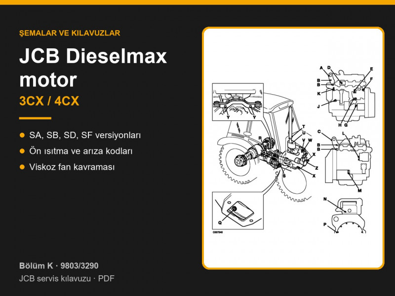
Engine overhaul is not part of this section: for full data and dismantling procedures the manual refers you to the separate engine manual, publication 9806/3000. Below you will find a page-by-page contents list and a summary of the most frequently needed data. Page numbers follow the manual’s own numbering (K-4, K-21 and so on).
Contents by Page — JCB 3CX / 4CX Engine
| Pages | What the section covers |
|---|---|
| K-1 – K-3 | Service tools, including the spanners for removing the cooling fan |
| K-4 | JCB Dieselmax technical data: SA, SB, SD and SF builds, power, displacement, valve clearances, oil pressure, engine speeds |
| K-5 – K-9 | Cold start heater: circuit, operation, fault codes, connectors and wiring |
| K-10 | Engine sensors and solenoids: list; replacement procedures are in the engine manual 9806/3000 |
| K-11 – K-12 | Engine bay support frame: removal for access to the top of the engine |
| K-13 – K-14 | Cooling fan viscous coupling: operation, fan removal and replacement |
| K-15 – K-19 | Radiator, expansion tank, coolant low level sensor |
| K-20 | Fuel injection pump: preparing the machine for removal |
| K-21 onwards | Engine removal and replacement: component locations, torque settings, sequence of work |
Which Engine Is Fitted to the JCB 3CX and 4CX
Machines in this series use the JCB Dieselmax, a 4.4 litre four-cylinder in-line diesel with direct injection and a mechanical rotary fuel injection pump (page K-4). The builds differ in aspiration and power output, from the naturally aspirated SA at 63 kW to the turbocharged and intercooled SF at 74 kW. The build is shown on the engine data plate, and it determines the compression ratio, the valve clearances and some of the parts.
| Build | Aspiration | Power | Compression ratio |
|---|---|---|---|
| SA | naturally aspirated | 63 kW (84 hp) | 18.6 : 1 |
| SB | turbocharged | 68 kW (92 hp) or 74 kW (100 hp) | 18.3 : 1 |
| SD | turbocharged | 63 kW (84 hp) or 68 kW (92 hp) | 17.2 : 1 |
| SF | turbocharged and intercooled | 74 kW (100 hp) | 17.2 : 1 |
JCB Dieselmax Technical Data
| Item | Value |
|---|---|
| Cylinders, bore × stroke | 4 in-line, 103 × 132 mm |
| Displacement | 4.4 litres |
| Firing order | 1-3-4-2, No. 1 cylinder at the crankshaft pulley end |
| Valves | 4 per cylinder |
| Valve clearances, engine cold, SA and SB | inlet 0.19–0.27 mm, exhaust 0.56–0.64 mm |
| Valve clearances, engine cold, SD and SF | inlet 0.35 mm, exhaust 0.56–0.64 mm |
| Oil pressure | 4.0–4.8 bar, engine warm, at maximum speed |
| Idle speed | 910 rev/min |
| Maximum governed speed / maximum no-load speed (pedal stop) | 2200 / 2350 rev/min |
| Dry engine weight | 472 kg (SA), 477 kg (SB, SD, SF) |
Viewed from the pulley end, the crankshaft rotates clockwise. Engine components are listed under JCB Dieselmax engine parts, and fuel injection pumps under fuel injection pumps.
Cold Start Heater and Fault Codes
To help cold starting, an electric air heater is fitted in the inlet manifold (page K-5). The control unit switches it on automatically when the sensor reads an air temperature below −6 °C. With the key turned to ON, the “engine not ready to start” lamp comes on; the heater runs for a set time, the lamp goes out and the engine can then be started. The heater stays on while the starter is cranking and switches off once the engine fires. The pre-heat stage can only be repeated after the key has been turned back to OFF.
Faults are signalled by the same lamp flashing on the side console (page K-6): one flash means an open circuit in the temperature sensor circuit, two a short circuit in the sensor circuit, three a faulty heater relay, and four an open or short circuit on the relay output. See sensors for sensors and relays for relays.
Cooling System: Viscous Coupling, Radiator, Expansion Tank
- Viscous fan coupling (page K-13) responds to the temperature of the air that has passed through the radiators. Below about 40 °C the coupling slips: at idle the fan turns at almost pulley speed, while at maximum engine speed it runs at about 45% of pulley speed. At around 65 °C the coupling locks and the fan turns at about 95% of pulley speed. The coupling is non-serviceable — if it fails, the fan assembly is replaced complete.
- Fan removal (page K-14) is carried out with special spanners, without removing the radiator or the oil cooler. The coupling has a left-hand thread.
- Radiator (page K-15) is part of the combined cooling pack and can only be removed after the hydraulic and transmission oil cooler. On machines with air conditioning the condenser is removed without disconnecting its hoses.
- Expansion tank (page K-17). When the engine is hot the cooling system is under pressure: remove the cap only once the engine has cooled down, otherwise hot coolant can cause burns. The coolant low level sensor is not fitted from machine serial number 976832; tighten it with great care — no more than 1/6 of a turn beyond the point of contact, or water will get into the sensor (page K-19).
Cooling system parts can be found under radiators, fans and expansion tanks.
Removing the Fuel Injection Pump and the Engine: Key Points
The fuel injection pump can be removed with the engine left in the machine (page K-20). The manual’s main warning: before the pump is removed, the engine and the pump must be mechanically locked in the correct position, otherwise it will not be possible to reset the injection timing. The procedures themselves and the torque settings are given in the engine manual 9806/3000.
The engine is removed with the gearbox disconnected from it (pages K-21 – K-24). First remove the engine bay support frame, bonnet, panels and the cooling pack. On machines with air conditioning, leave the refrigerant circuit sealed where possible; if it has to be opened, the refrigerant must be recovered by a qualified engineer. When the engine and gearbox are separated, the torque converter must stay on the gearbox shaft. Torque settings from the table on page K-22: engine mounting bolts 205 Nm, gearbox mounting bolts 237 Nm, engine lifting bracket bolts 50 Nm. On refitting, make sure the torque converter drive dogs engage correctly. Never work under raised loader arms unless the mechanical safety strut is fitted. To choose the right parts, send us the machine model and serial number together with the engine build from its data plate.
Parts enquiries