Below are the contents by page and a summary: how the steering works, what pressures it is set to, and what to check if the steering is heavy or the machine will not steer. Page numbers follow the manual (H-3, H-40 and so on).
Contents by page — JCB 3CX / 4CX steering
| Pages | What the section covers |
|---|---|
| H-1 – H-2 | Service tools |
| H-3 – H-5 | Technical data: steer unit, priority valve, priority valve on 3C sideshift machines |
| H-6 – H-13 | Basic operation: two wheel steer and four wheel steer (4WS) machines, steer modes, schematics with type 1 and type 2 steer mode valves |
| H-14 – H-32 | Circuit descriptions: steer unit in neutral and turning, shock valves, priority valve, steer mode electrics (relay PCB and ECU controlled), wires and connectors |
| H-33 – H-39 | Fault finding: five symptom tables and diagnostic blink codes from the warning light |
| H-40 – H-48 | Service procedures: standby pressure and steering pressure, priority valve cleaning, bleeding, re-phasing 4WS road wheels, proximity switch setting, solenoid checks, internal leakage checks |
| H-49 – H-54 | 3C sideshift machines: pressure tests and valve cleaning; priority valve removal and dismantling |
| H-55 – H-63 | Power track rod (axle steering ram), link arms, ram dismantling and assembly |
| H-64 – H-70 | Type 1 and type 2 steer mode valves: removal, dismantling and assembly |
| H-71 onwards | Steer unit: removal, replacement, dismantling and assembly |
How the JCB 3CX and 4CX steering works
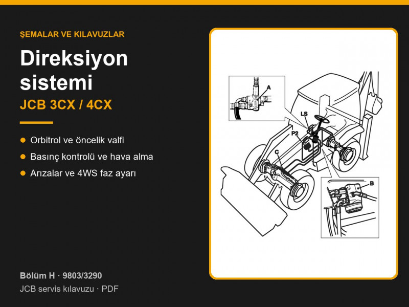
The steering system is fed by the second pump section, P2 (page H-6). When the operator turns the wheel, the steer unit sends a Load Sensing (LS) signal to the priority valve, which directs pump flow to the steer unit and from there to the ram on the front axle. When the turn is complete the signal disappears and the priority valve sends the flow to the main loader and excavator hydraulics. Maximum steering pressure is limited by a relief valve inside the steer unit.
Four wheel steer (4WS) machines also have a steer mode valve and a ram on the rear axle (pages H-7, H-8). Three modes are available: two wheel steer, four wheel steer for a tighter turning circle, and crab steer for diagonal travel. The mode changes only when the wheels are in the straight-ahead position, which is detected by proximity switches on the axles. As a result, the indicator on the panel may not match the switch position for a short time.
Steering pressures: technical data
| Component | Item | Value |
|---|---|---|
| Steer unit 160 OSPC | displacement / relief valve / shock valves | 160 cm³/rev / 120 ± 3 bar / 175–190 bar |
| Steer unit 200 OSPC | displacement / relief valve / shock valves | 200 cm³/rev / 120 ± 3 bar / 175–190 bar |
| Steer unit 250 OSPC | displacement / relief valve / shock valves | 250 cm³/rev / 120 ± 3 bar / not fitted |
| Priority valve | standby pressure | 7 bar; 18 bar for valve 35/910066, where fitted |
| Priority valve, 3C sideshift | standby pressure | 5.6 bar |
The relief valve pressure is given at an engine speed of 1500 rev/min (pages H-3 – H-5). Priority valves and steer units can be found in the hydraulic valves category, steering rams in JCB hydraulic rams.
Checking the steering pressures
- Standby pressure (page H-40). Warm the oil to 50 °C and turn the steering wheel several times in both directions to release pressure. Fit a 0–40 bar gauge to the priority valve test port, disconnect the LS hose and cap it. At 1000 rev/min the gauge should read 5.9–8.7 bar (5.6–8.7 bar on 3C sideshift machines, page H-49). If the pressure is out of limits, clean the priority valve first, then check the pump flow, and only then renew the valve.
- Steering pressure (page H-41). Connect a 0–400 bar gauge to the test point at the outlet of the P2 pump section. At 1500 rev/min hold the steering on full lock — the reading should equal the relief valve setting. Adjust it with an Allen key under the plug on the steer unit.
- Priority valve cleaning (page H-42). Remove the spool and spring, wash them in clean paraffin, paying particular attention to the holes in the spool ends, lubricate with hydraulic oil and refit the spool with its spring end towards the LS port. Tighten the plug and adapter to 50 Nm, then bleed the LS line until oil free of air bubbles comes out.
Before working under the machine, park it on level ground, lower the attachments, apply the park brake, chock all the wheels and disconnect the battery. If you have to work with the loader arms raised, fit the mechanical safety strut.
Heavy steering or machine will not steer: what to check
- Heavy steering (page H-34): tyre pressures, oil level, leaks at hoses and connections, air in the LS line, low pump flow, incorrectly set relief valve, worn steer unit, sticking priority valve or a leaking LS line. On 4WS machines also check for sticking spools or faulty solenoids in the steer mode valve, and for mechanical damage to the axles, link arms and rams.
- Steering turns on its own (page H-35): dirt in the steer unit, damaged or missing centring springs, rotor incorrectly assembled relative to the shaft slot.
- Machine will not steer (page H-36): the same causes as for heavy steering, plus the steering column splined shaft not fully engaged with the steer unit, and a damaged steering ram.
- Steer mode will not engage or wheels go out of phase (pages H-37, H-38, 4WS only): check the fuse, the 12 V supply at the connector and the solenoid coil resistance (page H-47). Wheels drifting out of phase quickly usually indicates internal leakage in the steering ram or the steer mode valve (page H-48).
On 4WS machines from serial number 1327630 the steer mode ECU reports faults by flashing the 2WS indicator (page H-39): one flash — solenoid “C” fault, two flashes — solenoid “D”, three flashes — steer mode relay, diode or their circuit. Valve solenoids are in the solenoids and valves category.
Bleeding the steering and re-phasing the wheels
After any steering component has been disconnected, the system must be bled before the machine is driven. On two wheel steer machines, at 1500 rev/min turn the steering to full lock left, then right, return to straight ahead and check the hydraulic tank level (page H-43). On 4WS machines bleeding follows the strict sequence on page H-45, alternating between 2WS and 4WS modes — do not change the order of the steps.
Over time the front and rear wheels of a four wheel steer machine drift slightly out of phase. The manual requires the phasing to be checked at the start of every shift, before driving on the road and at least once a day, as well as after 24 km of road travel in 2WS mode and after any steering repair (page H-44). To re-phase: select 2WS, drive until the rear wheels are straight, then select 4WS again. Track rods and track rod ends are in the front axle category, ram repair seals in hydraulic seal kits. To choose a part, send us the machine model, serial number and build: 2WS or 4WS.
Parts enquiries