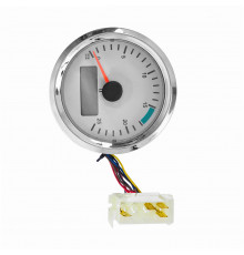
Below is a page-by-page contents list and a summary: the fuse table, relay functions and the test sequence for the battery, alternator and starter motor. Page numbers follow the manual’s own numbering (C-4, C-76 and so on).
Contents by Page — JCB 3CX / 4CX Electrics
| Pages | What the section covers |
|---|---|
| C-1 – C-2 | Service tools |
| C-3 – C-15 | Technical data: battery and alternator, 3CX and 4CX fuses and relays (early machines, to May 2009, from May 2009), transmission and steering relays, 3C-14 (214e) and 3C fuses and relays |
| C-16 – C-38 | Circuit diagrams for machines to May 2009 (analogue instruments): basic machine, Synchro Shuttle, Powershift and ShiftMaster transmission control, options — cold start, steer modes, brake modes, auxiliary hydraulics, SRS, return to dig, HSC, quickhitch |
| C-39 – C-58 | Circuit diagrams for machines from May 2009 (digital instrument panel) |
| C-59 – C-65 | Circuit diagrams for 3C-14 (214e) and 3C machines |
| C-66 – C-82 | Service procedures: using a multimeter, battery, alternator and starter motor testing, wire numbering, harness repair |
| C-83 – C-88 | Alternator and starter motor: removal, renewing the regulator and brushes, pulley, brush holder and solenoid |
| C-89 – C-90 | Earth point locations |
| C-91 – C-352 | 3CX and 4CX harnesses: harness interconnection diagrams and drawings for machines with mechanical controls and with joystick controls |
| C-353 onwards | 3C-14 (214e) and 3C harnesses |
JCB 3CX Electrical System: Key Data
The machine has a 12 V negative earth system (page C-3). The alternator’s rated output is 95 A. The manual gives two battery options: heavy duty, with a cold cranking current of 550 A at −18 °C and a reserve capacity of 220 minutes at a 25 A load, and temperate, with 410 A and 170 minutes. Circuit diagrams differ between machines built before and after May 2009: early machines have analogue instruments (page C-16), later ones a digital instrument panel (page C-39). Batteries can be found under batteries, alternators and starter motors under alternators and starter motors.
JCB 3CX and 4CX Fuse Table
On machines with lever controls (no joysticks) the main fuse box is in the side console under a cover (page C-4). Fuses are identified by a column letter (A, B, C) and a row number (1–10); some option fuses may not be fitted on a particular machine. For joystick (servo) machines the table is given in Section L, Servo Controls.
| No. | Circuit | A | No. | Circuit | A |
|---|---|---|---|---|---|
| A1 | Engine shut-off solenoid (ESOS) | 10 | B6 | Brake switch | 10 |
| A2 | Auxiliary hydraulics | 10 | B7 | Return to dig, SRS | 5 (10 with SRS and HBPV valves) |
| A3 | Direction indicators | 7.5 | B8 | Rear working lights | 25 |
| A4 | Steer mode proximity switches | 7.5 | B9 | Headlights | 20 |
| A5 | Transmission | 10 | B10 | Front working lights | 25 |
| A6 | Gear select (forward/reverse), lock-up torque converter speed sensors | 3 | C1 | Lights | 7.5 |
| A7 | Transmission | 10 | C2 | Hazard warning lights | 15 |
| A8 | Brake lights | 7.5 | C3 | Beacon, interior light | 10 |
| A9 / A10 | Side lights LH / RH | 5 / 5 | C4 | Radio | 5 |
| B1 | Instruments, buzzer | 5 | C5 | Thermostart | 3 |
| B2 | Front horn, front washer/wiper | 15 | C6 | Heater blower | 30 |
| B3 | Rear horn | 7.5 | C7 | Ignition relay coils | 3 |
| B4 | Heated seat, cigar lighter, face level fan | 15 | C8 | Main beam | 15 |
| B5 | Rear washer/wiper | 10 | C9 / C10 | Fog light / dip beam | 3 / 15 |
In addition to the main fuse box, a fuse link box is fitted on the engine compartment bulkhead (page C-6): 1 — hazard warning lights, beacon, lights — 40 A; 2 — wash/wipe, transmission, indicators — 50 A; 3 — work lights, fog lights, brake lights — 60 A; 4 — ignition, heater — 50 A; 5 — cold start air heater, if fitted — 150 A. The manual reminds you to replace a fuse only with one of the same rating and to find the cause before renewing a blown fuse. Fuse boxes and relays are listed under relays and fuse boxes.
JCB 3CX Relays: What Each One Does
The relays are in the side console under the same cover as the fuses. Their layout has changed over the years: early machines are shown on page C-7, machines to May 2009 on page C-8 and machines from May 2009 on page C-9. On machines from May 2009: 1 and 7 — ignition, 4 — direction indicators, 5 — hammer, 6 — auxiliary hydraulics (jaw bucket), 9 — neutral start, 11 — main lights, 12 — engine run, 13 and 19 — stabiliser leg alarm, 14 and 20 — front and rear working lights, 15 — rear horn, 16 — park brake warning light, 17 — hydraulic speed control (HSC), 18 — instrument panel buzzer, 21 — boom overload alarm. Transmission and steer mode relays are shown on page C-11.
Battery Testing
- Load test (pages C-70, C-71). The battery must be at least 75% charged and disconnected from the machine. Off-load voltage should be no less than 12.4 V, and after 5–10 seconds on load no less than 9 V. Do not keep the load applied for longer than 10 seconds. If the off-load reading is 6–12.4 V and the on-load reading below 9 V and falling steadily, recharge the battery and test it again; if it reads below 10 V off load and below 3 V on load, the battery is deeply discharged and is unlikely to recover.
- Specific gravity (page C-72) at 15 °C and ambient temperatures up to 27 °C: 1.270–1.290 — fully charged, 1.190–1.210 — half discharged, 1.110–1.130 — discharged. A difference of more than 0.04 between cells points to a faulty cell.
- Maintenance. Keep the terminals clean and coated with petroleum jelly, keep the electrolyte 6 mm above the plates and top up with distilled water only. A maintenance-free battery must not be fast-charged, charged above 15.8 V or charged further once it starts gassing.
- Safety. A battery gives off explosive gas, and the electrolyte is acid. Disconnect the negative lead first and reconnect the positive lead first.
Alternator Not Charging: Test Sequence
With the ignition switched on, the oil pressure and charge warning lamps should light, then go out quickly once the engine starts (page C-73). If the charge lamp stays on, check the battery voltage at the large terminals of the alternator connector with the engine stopped. Then carry out the output test (page C-74): fit a 100 A shunt into the positive lead, run the engine at maximum speed and take the reading straight away — the current should match the alternator’s maximum output. Zero output, in order of likelihood, means a defective suppression capacitor, dirty slip rings or worn brushes, or a faulty regulator, rectifier, rotor winding or stator winding.
The manual warns: never disconnect the battery or the alternator leads with the engine running, or the regulator or diodes will be damaged; disconnect the alternator connector before any welding on the machine; when jump starting from a slave battery, connect it in parallel — positive to positive, negative to negative.
Starter Motor Will Not Turn: Voltage Drop Test
Before testing (pages C-76, C-77), remove the engine shut-off fuse so that the engine cannot start, and put the direction lever in neutral. Do not operate the starter motor for more than 20 seconds at a time, and allow at least 2 minutes between attempts.
| Where to measure (key in START position) | Specification |
|---|---|
| Across the battery terminals | about 10.0 V, no less than 9.5 V |
| Between the starter motor main terminal and its body | no less than 9.0 V and no more than 0.5 V below battery voltage |
| At the solenoid terminal to earth | no less than 8.0 V |
| Between battery negative and starter motor earth | no more than 0.25 V |
| Between battery positive and starter motor main terminal | no more than 0.25 V |
If the solenoid receives less than 8 V, check the neutral start relay and the wiring from the direction selector: the relay terminal at which the voltage rises to 8 V shows where the open circuit is. A drop of more than 0.25 V in the heavy current circuits indicates a poor connection in the earth lead, the positive lead or the solenoid.
Reading Wire Numbers on JCB Circuit Diagrams
A wire’s number tells you what it does (page C-79): 000–099 — unfused ignition feeds, 100–199 — fused ignition feeds, 200–299 — unfused battery feeds, 300–399 — fused battery feeds, 400–599 — instrument and electronic system signal wires, 600–799 — earths, 800–999 — switched feeds to loads (lights and so on). A wire keeps its number through a connector, and wires at the same joint get a letter suffix: 640A, 640B and so on, without the letters I, O, Q and S. Harness repair is described on pages C-80 – C-82. Wires and connectors are listed under wiring, and all electrical parts under electrics for construction machinery. To choose a part, send us the machine model, serial number and year of manufacture.
Parts enquiries