
According to page 1-1, AMS is fitted to the JS200, JS210 and JS220 from serial number 706966 and to the JS240 and JS260 from serial number 709004. Earlier machines use CAPS II, and its diagnosis is described at the end of the section. Manual 9803/6400 applies to JS200 and JS220 machines from serial number 705001, JS210 from 705648, JS240 from 708001 and JS260 from 708501, including the long-track LC versions. Unless stated otherwise, data given for the JS200 also applies to the JS210 and JS220, and data for the JS240 also applies to the JS260.
Page guide: JCB JS200–JS260 electrics
| Pages | Contents |
|---|---|
| 1-1 | AMS system and the machines it applies to |
| 2-1 – 2-3 | Technical data, fuses, battery testing, wiring diagram and component list |
| 3-1 – 3-6 | Cab, right and left consoles, monitor, switch functions |
| 4-1 – 4-14 | Engine control: throttle stepper motor, engine stop, back-up control, auto adjustment, auto idle, engine speed by mode, breaker engine speed, auto warm-up, reverse rotation protection |
| 5-1 – 5-25 | Pump control: boom soft lowering and soft start, power boost, three travel speeds, soft/hard mode, slew brake and slew lock, lever lockout, travel alarm, display |
| 6-1 – 7-1 | Throttle motor replacement and auto calibration, engine speed sensor installation |
| 8-1 | Self-diagnosis |
| 9-1 – 9-19 | Fault finding by monitor messages, temperature sensor resistance |
| 10-1 onwards | CAPS II system diagnosis |
Technical data and fuses
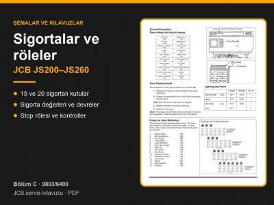
The electrical system is 24 V. The work lights on the tank and boom are 24 V, 70 W, and the cab interior light is 10 W (page 2-1). The fuses are in a fuse box on the rear console. If a fuse blows repeatedly or the cause is unclear, check the circuit. Fuse layout for later machines:
| No. | Circuit | Rating, A |
|---|---|---|
| 1 | Radio, cigar lighter | 10 |
| 2 | Beacon | 10 |
| 3 | Fuel pump | 20 |
| 4 | Additional work lights | 15 |
| 5 | Standard work lights | 15 |
| 6 | Horn, interior light | 10 |
| 7 | Back-up power | 10 |
| 8 | Ignition switch | 10 |
| 9 | Engine stop | 15 |
| 10 | Controller power supply | 15 |
| 11 | Controller control | 10 |
| 12 | Lever lockout | 10 |
| 13 | Heater | 20 |
| 14 | Wiper, washer | 10 |
| 15 | Spare | 10 |
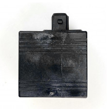
Earlier machines have a different layout, shown on the same page. Fuses and relays are in the relays and electrics categories.
Operating modes and engine speeds
- When the ignition is switched on, the machine is in standard S mode: engine speed is 100 rev/min below maximum (H mode). In L and F modes engine speed is 200 rev/min below maximum (page 4-11).
- Auto idle: if all hydraulic functions are inactive in this mode, the engine drops to idle after 15 seconds. Idle can only be cancelled with the idle button (page 4-10).
- Auto warm-up engages when coolant temperature is below 50 °C, the excavator end and travel are not being used, manual idle is off, 12 seconds have passed since starting and the throttle dial has not been touched (page 4-13).
- Hydraulic breaker: when the breaker pedal is pressed, the controller lowers engine speed to the value preset in set-up mode and restores it when the pedal is released (page 4-12).
- Power boost: in H and S modes, a button on the right-hand joystick raises the main relief valve setting for 8 seconds, and a message is shown on the monitor during this time. When travelling, pressure is raised automatically while the travel pressure switch is on (page 5-7).
- Three travel speeds: after the ignition is switched on, medium speed is selected; pressing the button selects high speed (travel motor swashplate at minimum displacement), and pressing it again selects low speed with pump flow cut (page 5-10).
- Slew brake: with the slew lever in neutral the brake works at 50% force, and with the slew lock engaged at 100% (page 5-17).
Monitor messages and what to check
If a message stays on the monitor after the cause has been removed, the manual refers you to a problem number with a step-by-step check of the sensor, wiring and controller (page 9-2):
| Message | When it indicates a fault | No. |
|---|---|---|
| Engine emergency stop | stays on with the emergency stop button released | 1 |
| Refuel | stays on after refuelling | 2 |
| Top up coolant | stays on after topping up | 3 |
| Air filter blocked | stays on after the filter has been cleaned | 5 |
| Low engine oil pressure | stays on with the oil level correct; checked 12 seconds after starting | 6 |
| Engine oil filter blocked | stays on after the filter and oil have been changed | 7 |
| Overheat | stays on with hydraulic oil below 84 °C and coolant below 92 °C | 8 |
| Battery not charging | stays on | 9 |
| Electrical system fault | stays on; engine speed does not respond to the throttle dial, engine will not start | 10–12 |
Test values
- Battery voltage with the engine stopped: 25–26 V.
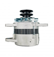
- Alternator voltage above half engine speed: 27.5–29.5 V. Immediately after starting with a discharged battery it may be about 25 V (page 9-3).
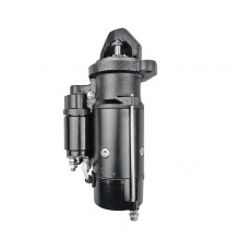
- Before fault finding, check the fuel, hydraulic oil, gearbox and engine oil and coolant levels, the air filter indicator, the battery, alternator and starter motor terminals, the condition of the wiring and connectors, and the fuses.
Coolant and oil temperature sensor resistance (page 9-19):
| Temperature | 20 °C | 30 °C | 40 °C | 50 °C | 60 °C | 70 °C | 80 °C |
|---|---|---|---|---|---|---|---|
| Resistance, kΩ | 8.00–10.20 | 5.35–6.50 | 3.60–4.55 | 2.50–3.10 | 1.70–2.20 | 1.20–1.55 | 0.85–1.15 |
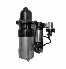
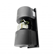
Sensors are in the sensors category, alternators and starter motors in the alternators and starter motors categories, batteries in the batteries category, and throttle motors in the electric motors category.
Other sections of the JCB JS200–JS260 manual: routine maintenance, hydraulics, undercarriage, travel motor and gearbox, Isuzu 6BG1T engine, mainframe, cab and component weights, torque settings and sealants. To choose a part, send us the machine model, serial number and the JCB part number if you know it.
Parts enquiries