Manual 9803/6400 applies to JS200 and JS220 machines from serial number 705001, JS210 from 705648, JS240 from 708001 and JS260 from 708501, including the long-track LC versions. Unless stated otherwise, data given for the JS200 also applies to the JS210 and JS220, and data for the JS240 also applies to the JS260.
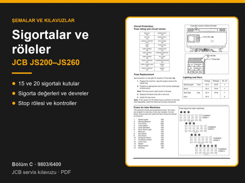
Fuse box location
The fuse box is on the rear console of the cab, behind a cover. The machine has a 24 V electrical system. Page 2-1 gives the replacement procedure: stop the engine and remove the starter key, have a fuse of the correct amperage ready, remove the cover (its right-hand corner is the grip), replace the blown fuse and refit the cover. If the reason for the blown fuse is unknown or the fuse fails repeatedly, the manual says to check the circuit concerned rather than fit a higher-rated fuse.
JCB JS200–JS260 fuses, later machines (15 fuses)
Layout for later machines, Section C, page 2-1:
| No. | Circuit | Rating, A |
|---|---|---|
| 1 | Radio, cigar lighter | 10 |
| 2 | Warning beacon | 10 |
| 3 | Fuel pump | 20 |
| 4 | Auxiliary lamps | 15 |
| 5 | Standard lamps | 15 |
| 6 | Horn, cab light | 10 |
| 7 | Back-up supply | 10 |
| 8 | Starter switch | 10 |
| 9 | Engine shut-down | 15 |
| 10 | Controller power (Computer P.) | 15 |
| 11 | Controller control (Computer C.) | 10 |
| 12 | Lever lock | 10 |
| 13 | Heater | 20 |
| 14 | Wiper, washer | 10 |
| 15 | Auxiliary | 10 |
Fuses on early machines (20 fuses)
Early machines have a different box with two rows of ten fuses. The circuit names are printed on the box cover; the table gives them as marked, with a plain description alongside (page 2-1):
| Marking | Circuit | Rating, A | Marking | Circuit | Rating, A |
|---|---|---|---|---|---|
| BACK UP | Back-up supply | 10 | COMPUTER P. | Controller power | 15 |
| KEY SW. | Starter switch | 10 | COMPUTER C. | Controller control | 10 |
| AIRCON., HEATER | Air conditioning, heater | 20 | SHUT DOWN | Engine shut-down | 15 |
| LAMP | Lamps | 15 | LEVER LOCK | Lever lock | 10 |
| LAMP (SPARE) | Lamps, spare | 15 | LUBRICATOR | Automatic lubrication | 10 |
| LAMP (SPARE) | Lamps, spare | 15 | WARNING BEACON | Warning beacon | 10 |
| LAMP (SPARE) | Lamps, spare | 15 | OIL PUMP | Pump (oil pump) | 20 |
| WIPER, WASHER | Wiper, washer | 15 | CONDENSER MOTOR | Condenser fan motor | 15 |
| HORN, ROOM LAMP | Horn, cab light | 10 | SPARE | Spare | 10 |
| RADIO, LIGHTER | Radio, cigar lighter | 10 | SPARE | Spare | 10 |
The quickest way to tell which layout a particular machine has is to look at the fuse box cover, which shows the circuit names and ratings. If the markings have worn off, count the fuse positions: there will be either 15 or 20.
Relays and fusible links on the schematic
The relay list is taken from the key to the electrical schematic on page 2-3. The item numbers match the references on the schematic in the PDF:
| Item | Relay |
|---|---|
| 20A, 20B, 20C | Fan 1, 2, 3 |
| 20D | Horn |
| 20E | Horn volume |
| 20F | Screenwasher |
| 20G | Screenwiper |
| 20H | Lamp (boom) |
| 20J | Auxiliary lamps (optional) |
| 20K | Cab light |
| 20L | Lever lock |
| 20M | Engine shut-down 1 |
| 20N | Engine shut-down 2 |
| 32 | Battery relay (earth) |
| 45 | Glow plug relay |
In addition to the fuses in the box, the circuits are protected by fusible links: 30A for the starter switch and back-up fuses, 30B for the engine shut-down fuse and 31 for the fuse box supply. If a whole group of consumers stops working but the fuses in the box are intact, check the fusible links next.
Checking the engine shut-down circuit
On the JS the engine is stopped by the engine shut-down motor, which the controller operates through two shut-down relays (20M and 20N). If the monitor displays the “Emergency engine stop” message with the button released, or the engine will not start, the fault finding pages (9-4 and 9-17) give the following sequence:
- make sure the fuses in the fuse box are serviceable;
- with the starter switch ON and the shut-down relay 1 connector plugged in, measure the voltage on wire LW — it should be 20–30 V;
- disconnect the shut-down relay 1 connector and measure the coil resistance between terminals 1 and 2 on the relay side — the manual gives approximately 250 ohms;
- check the voltage on wire L of shut-down relay 1: 0 V with the emergency stop button pressed and 20–30 V with it released;
- to tell a faulty relay from a wiring fault, the manual suggests temporarily swapping the suspect relay with an identical one from the relay box.
The operating logic, monitor messages and sensor checks are covered in detail in our article on JCB JS200–JS260 electrics and the AMS system.
Where to find parts
Relays are in the relays category, wiring looms and connectors in wiring, switches in switches, and lamps and beacons in the lighting and beacons categories. The other sections of the manual are collected on the JCB JS200–JS260 manuals page. To choose a part, send us the machine model, serial number and the JCB part number if you know it.
Parts enquiries