
Manual 9803/6400 applies to JS200 and JS220 machines from serial number 705001, JS210 from 705648, JS240 from 708001 and JS260 from 708501, including the long-track LC versions. Unless stated otherwise, data given for the JS200 also applies to the JS210 and JS220, and data for the JS240 also applies to the JS260.
Page guide: JCB JS200–JS260 Sections 1 and 2
| Pages | Contents |
|---|---|
| Section 1, 1-1 | Torque settings for bolts and nuts on the main assemblies; general table for M6–M20 bolts |
| Section 1, 4-1 | Electrical service tools: instrument case, tester, temperature probes, tachometer, multimeter, battery tester |
| Section 1, 5-1 – 5-4 | Hydraulic tools: pressure gauge tees and adapters, 0–400 bar and 0–70 bar gauges, hand pump, tools for the swing motor and rams |
| Section 1, 6-1 – 6-3 | Tools for overhauling the travel motor and final drive gearbox |
| Section 1, 7-1 | JCB sealants, threadlockers and other compounds |
| Section 2, 1-1 – 4-2 | Safety: warning labels, general safety, operating the machine, maintenance (soft ground, welding, etc.) |
When to check bolt torques
The manual says bolts and nuts should be checked for looseness or loss before and after each shift. Loose fasteners are retightened and missing ones replaced. A full retorque is required after the first 50 hours of running-in and then every 250 hours (page 1-1). Tapping the fasteners with a hammer during the daily inspection helps to find any that have worked loose.
Torque settings for the main assemblies of the JCB JS200–JS260
Values from the table on page 1-1. Items marked † must have threadlocker applied before tightening; the manual specifies Loctite 262.
| No. | Assembly | Thread / spanner | Torque, Nm |
|---|---|---|---|
| 1† | Travel motor | M16 / 24 mm | 270–310 |
| 2† | Sprocket | M16 / 24 mm | 270–310 |
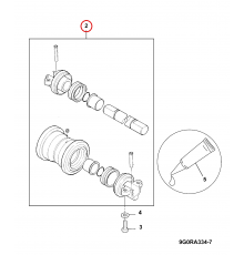
| 3† | Idler | M16 / 24 mm | 270–310 |
| 4† | Top (carrier) roller | M20 / 30 mm | 520–608 |
| 5† | Bottom (track) roller | M18 / 27 mm | 370–430 |
| 6† | Track guard | M18 / 27 mm | 380–440 |
| 7 | Track shoe bolt | M16 / 24 mm | 380–450 (Section J gives a different value, see below) |
| 8 | Counterweight | M27 / M30 | 1058–1235 / 1335–1545 |
| 9† | Slew ring to undercarriage frame | M20 / M24 | 475–550 / 780–910 |
| 10† | Slew ring to upper structure | M20 / M24 | 475–550 / 780–910 |
| 11† | Slew gearbox | M20 / M24 | 525–605 / 785–910 |
| 12† | Engine mounts | M16 / 24 mm | 265–310 |
| 13† | Engine bracket | M10 / 17 mm | 65–75 |
| 14 | Radiator | M16 / 24 mm | 150–175 |
| 15† | Hydraulic pump | M10 / 17 mm | 65–75 |
| 16† | Hydraulic tank | M16 / 24 mm | 235–285 |
| 17† | Fuel tank | M16 / 24 mm | 255–285 |
| 18† | Control valve | M16 / 24 mm | 270–310 |
| 19† | Rotary coupling | M12 / 19 mm | 110–125 |
| 20 | Cab | M16 / 24 mm | 127–135 |
| 21 | Battery | M10 / 17 mm | 20–30 |
For the track shoe bolt, Section 1 gives 380–450 Nm with an M16 thread, whereas the table in Section J “Track and Running Gear” gives 775.1–931.6 Nm. Before tightening, confirm the actual bolt size and part number; more on this in the article on the JCB JS200–JS260 undercarriage.
General torque table for M6–M20 bolts
For fasteners not listed in the assembly table, the manual gives general values:
| Thread | M6 | M8 | M10 | M12 | M14 | M16 | M18 | M20 |
|---|---|---|---|---|---|---|---|---|
| Spanner, mm (hexagon head) | 10 | 13 | 17 | 19 | 22 | 24 | 27 | 30 |
| Torque, Nm (hexagon head) | 6.9 | 15.7 | 32.3 | 58.8 | 98.0 | 137.2 | 196.0 | 274.4 |
| Hexagon key, mm (socket head) | 5 | 6 | 8 | 10 | 12 | 14 | 14 | 17 |
| Torque, Nm (socket head) | 8.8 | 21.6 | 42.1 | 78.4 | 117.6 | 176.4 | 245.0 | 343.0 |
JCB sealants and threadlockers
The table on page 7-1 shows which compound to use for each type of joint:
| Compound | Application | JCB part no. |
|---|---|---|
| JCB Multi-Gasket | medium-strength sealant for gasketed flanges of any size and hydraulic fittings 25–65 mm | 4102/1212 (50 ml) |
| JCB Threadlocker | for threads of 50 mm diameter and above, e.g. strainer | 4101/0451 (50 ml) |
| JCB Threadlocker (High Strength) | high-strength locking of threaded parts; sealing flanges where joint strength matters | 4102/0551 (50 ml) |
| JCB Retainer (High Strength) | for permanent fits | 4101/0651 (50 ml) |
| JCB Threadlocker and Sealer | medium strength: bolts, nuts and screws up to 50 mm, hydraulic fittings up to 25 mm | 4101/0250 (10 ml), 4101/0251 (50 ml) |
| JCB Threadlocker and Sealer (High Strength) | high strength: bolts, nuts and screws up to 50 mm, hydraulic fittings up to 25 mm | 4101/0550 (10 ml), 4101/0552 (200 ml) |
| JCB Threadseal | medium-strength thread sealant | 4102/1951 (50 ml) |
You will find sealants and threadlockers in the sealants category and bolts and nuts in the fasteners category.
Hydraulic service tools
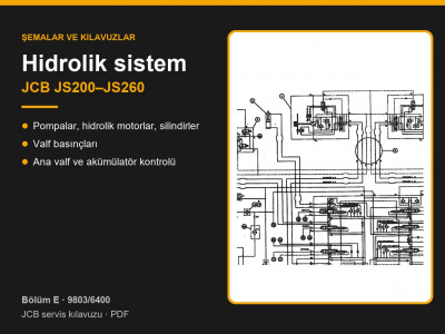
To check pressures, the manual uses a 0–400 bar gauge (892/00279) for the working circuits and a 0–70 bar gauge (892/00346) for the servo circuit, plus a set of tees and adapters for the test points with 1/4 in to 1 1/2 in BSP threads (page 5-1). The procedure for checking the main relief valve is described in the article on JCB JS200–JS260 hydraulics.
Other sections of the JCB JS200–JS260 manual: routine maintenance, hydraulics, electrics and AMS, undercarriage, travel motor and gearbox, Isuzu 6BG1T engine, mainframe, cab and component weights. To choose a part, send us the machine model, serial number and the JCB part number if you know it.
Parts enquiries