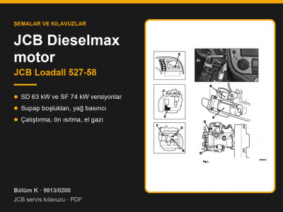
The Loadall 527-58 covered by manual 9813/0200 is a compact telehandler with hydrostatic transmission. The machine variants table (page 1-2-1) lists two JCB Dieselmax engines: the turbocharged SD rated at 63 kW (85 hp) and the turbocharged, charge-cooled SF rated at 74 kW (100 hp). Maximum travel speed depends on the transmission version: 20, 25, 34 or 40 km/h.
Page-by-page contents: Sections 1 and 2, JCB Loadall 527-58
| Pages | What the section covers |
|---|---|
| 1-2-1 | Machine variants: engines, transmissions, options |
| 1-3-1 – 1-3-8 | Machine and component identification |
| 1-4-1 – 1-4-8 | Fuel: acceptable grades, additives, B20, sulphur |
| 1-5-1 – 1-5-10 | Torque settings: fasteners and hydraulic connections |
| 1-6-1 – 1-7-2 | Service tools, sealants and retainers |
| 2-1-1 – 2-1-14 | Warnings and safety checklist |
| 2-2-1 – 2-2-20 | General procedures: parking, boom support, pressure release, hydraulic hoses, batteries, rams |
How to decode the machine number (PIN)
The machine data plate shows the PIN, the serial numbers of the engine, transmission and axles, plus power, weight, rated load and year of manufacture (page 1-3-3). The PIN is made up as follows:
| Part | Meaning |
|---|---|
| WMI | 3 characters — manufacturer code |
| Model | 5AT — 527-58 with low cab, 5AV — with high cab |
| Engine | S — 74 kW (100 hp), T — 63 kW (85 hp) |
| Transmission | P — 20 km/h, R — 25, S — 34, T — 40 km/h |
| Check letter | 1 character |
| Serial number | 8 digits |
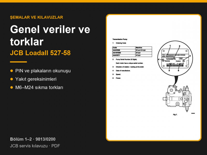
Engine number labels are fitted to the cylinder block and the rocker cover, and the last part of the number is stamped on the block itself. The manual's example is SD 320/40001 U 00001 09, where S is the 4.4 litre series, D means turbocharged, F turbocharged and charge-cooled, U built in the United Kingdom, and the final digits give the year (page 1-3-4). The transmission pump is identified by the code on its plate: AA4VG56 for the 20 and 34 km/h versions, AA10VG63 for 25 km/h and AA4VG71 for 40 km/h.
Fuel
Fuel to EN590, BS2869 A2, ASTM D975-91 Class 2 and JIS K2204 can be used without restriction. B20 biodiesel (up to 20 % rapeseed methyl ester) is permitted only on engines built from 2007 onwards, and only if the engine oil is at least CH4, the oil and filter change intervals are at least halved and every fifth fill is pure diesel. Sulphur content affects the oil change interval: up to 0.5 % — normal interval, 0.5–1.0 % — 0.75 of the interval, above 1.0 % — half the interval (pages 1-4-3 – 1-4-7). Unprocessed vegetable oils must not be used.
Torque settings for metric fasteners
Tolerance is ±3 %. Condition 1 applies to non-lubricated fasteners with zinc or yellow plating; condition 2 applies to Dacromet fasteners, lubricated zinc-plated fasteners and fasteners threaded into cast iron (pages 1-5-2 – 1-5-4):
| Thread | 8.8 (cond. 1 / 2) | 10.9 (cond. 1 / 2) | 12.9 (cond. 1 / 2) |
|---|---|---|---|
| M6 | 9.9 / 9.0 | 13.9 / 12.5 | 16.6 / 15.0 |
| M8 | 24 / 22 | 34 / 30 | 40 / 36 |
| M10 | 47 / 43 | 67 / 60 | 80 / 72 |
| M12 | 83 / 74 | 116 / 104 | 139 / 125 |
| M16 | 205 / 184 | 288 / 259 | 345 / 311 |
| M20 | 400 / 360 | 562 / 506 | 674 / 607 |
| M24 | 690 / 621 | 971 / 874 | 1165 / 1048 |
Hydraulic torque settings: BSP adapters into housings from 18 Nm (1/4") to 206 Nm (1 1/4"), BSP hoses from 24–27 to 244–260 Nm, positional adapter locknut 81 Nm (pages 1-5-6 – 1-5-10).
Safe maintenance rules
- Before any maintenance, park the machine on firm, level ground, lower the attachment, stop the engine, apply the park brake, release the pressure and remove the key (page 2-2-3).
- Never work under a raised boom unless the service support is fitted on the lift ram rod (page 2-2-4).
- Before disconnecting hoses, release hydraulic pressure by operating the controls with the ignition on; open the tank cap slowly (page 2-2-6).
- Disconnect the battery negative lead first and reconnect it last; before welding, disconnect the battery and the alternator (pages 2-2-15, 2-2-16).
- According to JCB, 70 % of hydraulic component failures are caused by contaminated fluid, so always cap or plug open ports (page 2-2-13).
Fasteners can be found under fasteners, adapters and pipes under hose connectors and pipes.
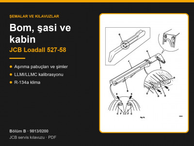
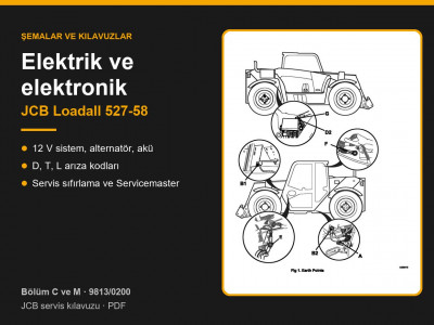
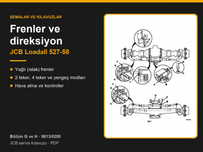
Other sections of the JCB Loadall 527-58 service manual: routine maintenance, hydraulics, transmission and axles, brakes and steering, engine, electrics and electronics, boom, chassis and cab. To choose a part, send us the machine model, the serial number and the JCB part number if you know it.
Parts enquiries