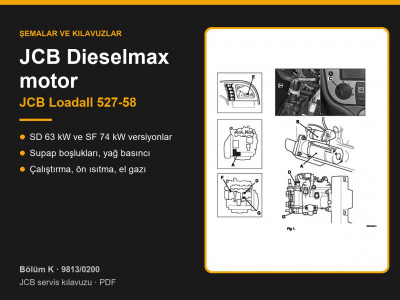
Manual 9813/0200 applies to the Loadall 527-58 compact telehandler with hydrostatic transmission. According to the applicability table on page 1-2-1, the machine was fitted with JCB Dieselmax SD engines rated at 63 kW (85 hp), turbocharged, or SF engines rated at 74 kW (100 hp), turbocharged and charge-air cooled. The transmission was built in four maximum speed versions: 20, 25, 34 and 40 km/h.
Section F page guide: JCB Loadall 527-58 transmission
| Pages | Contents |
|---|---|
| F1-1 – F1-6 | Wheels and tyres, wheel nut torques |
| F2-1 – F2-8 | Front axle |
| F3-1 – F3-8 | Rear axle |
| F4-1 – F4-70 | Hydrostatic transmission: data, hydraulics, electrics, fault finding, test procedures, priming, moving a disabled machine |
| F5-1 – F5-8 | Dual control system (direction selection) |
| F6-1 – F6-14 | Hydrostatic drive motor |
| F7-1 – F7-10 | Hydrostatic drive pump |
| F8-1 – F8-4 | Propshafts |
| F9-1 – F9-8 | Speed sensors |
| F10-1 – F11-4 | Transmission ECU and transmission manifold |
How the Loadall 527-58 transmission works
The circuit is a closed loop and works in both directions; the pump and motor are both variable displacement axial piston units. With the machine stationary, pressure is equal in both lines and the motor is hydraulically locked (page F4-7). The motor drives a gearbox with an output shaft: one end carries the rear propshaft flange, the other a flange on the brake disc, from which the front propshaft is driven (page F4-23). There are no mechanical gears, only the tortoise / hare range selection and direction of travel. An accumulator in the circuit smooths out pressure spikes.
Hydrostatic pumps by speed version
The pump version is identified by the colour marking on the drive motor (pages F4-3, F4-4). Maximum charge pressure is 30 bar on all pumps:
| Speed | Pump, control | Displacement | Charge pump | Pressure limit | Motor marking |
|---|---|---|---|---|---|
| 20 km/h | AA4VG56, EP | 56 cc/rev | 11.6 cc/rev | 480 bar | green |
| 25 km/h | AA10VG63, DA | 63 cc/rev | 14.9 cc/rev | 350 bar | grey |
| 34 km/h | AA4VG56, EP | 56 cc/rev | 11.6 cc/rev | 480 bar | blue |
| 40 km/h | AA4VG71, EP | 71 cc/rev | 19.6 cc/rev | 480 bar | black |
DA control (25 km/h): charge pressure rises with engine speed and moves the swashplate control piston. Under load, engine speed drops, the swashplate angle reduces and power is automatically shared between drive and hydraulics. EP control (20, 34 and 40 km/h): the transmission ECU operates the pump's proportional solenoids with a PWM signal, and a feedback lever tells the ECU the position of the piston (pages F4-10 – F4-13).
Hydrostatic drive motor
| Item | Value |
|---|---|
| Type | bent axis axial piston, variable displacement, chassis mounted |
| Displacement | 233 cc/rev maximum, 36 cc/rev minimum |
| Maximum flow | 400 l/min |
| Pressure | up to 480 bar in the circuit, up to 5 bar in the case |
| Maximum torque | 2560 Nm |
| Speed | 1800 rev/min at maximum angle, 4200 rev/min at minimum angle |
| Gearbox | 1 : 1.64 |
| Dry weight | approx. 140 kg |
Data from page F4-5. The motor carries a flushing valve, which bleeds off part of the oil from the low pressure line to stop the hydrostatic system overheating, a pressure cut-off valve and a circuit that prevents motor displacement from increasing when driving downhill. In the tortoise range the ECU energises the low speed solenoid and the motor runs at maximum angle: low speed, high torque. If tortoise is selected at more than 20 km/h, the ECU will not engage it and gives a warning (page F4-33).
Pressure testing
Warm the oil to 50 °C before testing. Do not hold the transmission stalled in gear for more than 10 seconds (pages F4-50, F4-63).
| Test point | Condition | Specification |
|---|---|---|
| G: charge pressure | idle 900 rev/min / 2300 rev/min | 25 ± 2 bar / 30 ± 2 bar |
| PS: control pressure | idle / 2300 rev/min | 5 ± 2 bar / 30 ± 2 bar |
| Ma / Mb: high pressure at stall | 25 km/h / 20, 34, 40 km/h | 350 bar / 450 bar |
| Charge pressure, maximum | 40 bar | |
| Case and drain | 3 bar |
The DA valve is working correctly if the wheels start to turn at 1000–1100 rev/min engine speed (page F4-65). Motor solenoid resistance: reverse 6–6.5 Ω, low speed 5 ± 2 Ω, 12 V supply (page F4-67). If the oil temperature exceeds 95 °C (sensor on the hydraulic filter housing), a limp mode with reduced speed is engaged.
Axles and propshafts
- Front axle: SD55 steer drive axle with D55 epicyclic hub reductions and oil-immersed multi-plate brakes in the centre section. The torque proportioning differential keeps drive on one wheel when the other is slipping (pages F2-3, F2-4).
- Rear axle: SD55 one-piece axle, oscillating on trunnions (page F3-3). The axle ratio must match the gearbox ratio: never fit an axle with a different ratio.
- Torque settings: wheel nuts 680 Nm, rechecked every 2 hours after fitting (page F1-4); front axle mounting bolts 621, 70 and 83 Nm depending on position, rear axle 360 Nm with thread locker (pages F2-6, F3-6).
- Propshafts: mark the flanges before removal, grease the splines, align the yokes at both ends in the same plane and always fit new front shaft straps (page F8-3). With the propshafts removed, the park brake does not work.
- Transmission speed sensor gap: 0.5–1.0 mm (page F9-5).
Priming and towing
Before starting, fill a new pump with 2 l of oil and top up the tank through a 10 micron filter without bypass. Charge pressure during priming must be at least 2.5 bar; then run the transmission through ten cycles in all directions at idle (page F4-68). With the propshafts in place, the machine may be towed no further than 25 m and no faster than 1 km/h (page F4-69). The manual does not cover dismantling the complete pump or motor; only the externally mounted components are replaced.
Transmission parts are listed under transmission and gearbox, hydraulic pumps under hydraulic pumps, propshafts and universal joints under driveshafts, propshafts and universal joints, and axle parts under front axle and rear axle.
Other sections of the JCB Loadall 527-58 manual: routine maintenance, general data and torque settings, hydraulics, brakes and steering, engine, electrics and electronics, boom, chassis and cab. To choose the right part, send us the machine model, the serial number and the JCB part number if you have it.
Parts enquiries