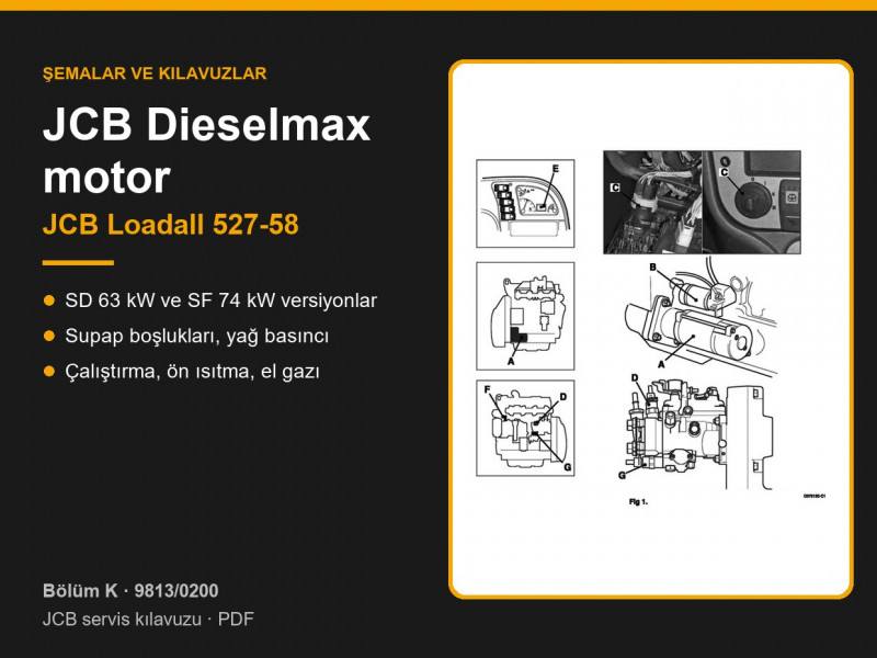
Service manual 9813/0200 covers the compact Loadall 527-58 telehandler with hydrostatic transmission. According to the applications table (page 1-2-1), the machine was built with JCB Dieselmax SD engines rated at 63 kW (85 hp), turbocharged, and SF engines rated at 74 kW (100 hp), turbocharged and charge-air cooled, and with the transmission in four maximum speed options: 20, 25, 34 and 40 km/h. Full overhaul information for the engine itself is published separately by JCB as publication 9806/3000.
Contents by page – JCB Loadall 527-58 engine
| Pages | What the section covers |
|---|---|
| K1-1 – K1-6 | Start and stop system |
| K2-1 – K2-6 | Cold start heater |
| K3-1 – K3-10 | Dieselmax engine: specifications, removal and replacement |
| K4-1 – K4-6 | Starter motor |
| K5-1 – K5-6 | Cooling pack |
| K6-1 – K6-4 | Coolant expansion tank |
| K7-1 – K7-4 | Exhaust silencer |
| K8-1 – K8-4 | Air filter vacuum switch |
| K9-1 – K9-6 | Throttle pedal and cable |
| K10-1 – K10-10 | Hand throttle |
Engine specifications
| Item | Value |
|---|---|
| Versions | SD – 63 kW (85 hp), turbocharged; SF – 74 kW (100 hp), turbocharged and intercooled |
| Dry weight | 477 kg |
| Cylinders | 4 in-line, 4 valves per cylinder |
| Bore × stroke | 103 × 132 mm |
| Displacement | 4.4 litres |
| Compression ratio | 17.2 : 1 |
| Firing order | 1-3-4-2, No. 1 cylinder at the pulley end |
| Valve clearances (cold) | inlet 0.35 mm, exhaust 0.56–0.64 mm |
| Oil pressure | 4.0–4.8 bar, engine hot, maximum speed |
| Fuel injection | direct, mechanical rotary injection pump |
| Idle speed | 900 rev/min |
Data from page K3-3. SD and SF are the first two letters of the engine number on the data plate: the first letter, S, stands for 4.4 litres and the second gives the aspiration type.
Starting, cold start aid and stopping
- The starter motor and its solenoid are energised with the key at position III and only with the transmission in neutral; above 600 rev/min the neutral start relay is switched off (page K1-3).
- A cold start solenoid on the injection pump is controlled by the coolant temperature switch.
- The grid heater in the inlet manifold switches on automatically when the air temperature is below −6 °C, and a warning light is on before starting (page K2-3).
- The engine is stopped by the electric shut-off solenoid (ESOS) when the key is turned to position O.
Engine removal and component service
- The engine can only be removed together with the hydrostatic pump, using a crane and lifting beam. Before that, recover the air conditioning refrigerant, remove the cooling pack, expansion tank and silencer, and drain the hydraulic system (page K3-4).
- On refitting, torque the pump hose banjo bolts to 65 Nm on 40 km/h machines and to 42 Nm on 20, 25 and 34 km/h machines, then bleed the pump and check the throttle cable.
- Starter motor: renew the brushes when they are shorter than 8 mm; mounting bolts 47 Nm (page K4-3).
- Cooling pack combines the coolant radiator, charge air cooler, hydraulic fan (reversible as an option) and oil cooler, and is removed as one assembly (page K5-3).
- Exhaust silencer: nuts 22–26 Nm, always fit a new gasket (page K7-3).
- Throttle pedal: stop screw protrudes 28 mm, limit switch plunger travel 2–4 mm (page K9-4).
- Hand throttle: the lever sensor signals the hydraulics ECU, which drives an actuator on the injection pump lever. If the lever is not at minimum when the ignition is switched on, the hand throttle will not work. To calibrate, move the lever to maximum and then back to minimum (page K10-3).
Engine parts are listed under JCB Dieselmax engine, starter motors under starter motors, radiators under radiators and filters under genuine JCB filters.
Other sections of the JCB Loadall 527-58 manual: routine maintenance, general data and torque settings, hydraulics, transmission and axles, brakes and steering, electrics and electronics, boom, mainframe and cab. To choose a part, send us the machine model, serial number and the JCB part number if you know it.
Parts enquiries