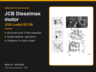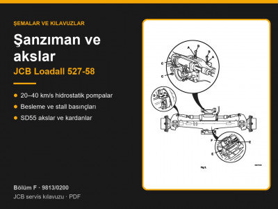
Manual 9813/0200 applies to the Loadall 527-58 compact telehandler with hydrostatic transmission. According to the applicability table on page 1-2-1, the machine was fitted with JCB Dieselmax SD engines rated at 63 kW (85 hp), turbocharged, or SF engines rated at 74 kW (100 hp), turbocharged and charge-air cooled. The transmission was built in four maximum speed versions: 20, 25, 34 and 40 km/h.
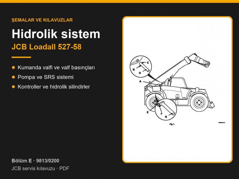
Section E page guide: JCB Loadall 527-58 hydraulics
| Pages | Contents |
|---|---|
| E1-1 – E1-4 | Hydraulic schematic and component key |
| E2-1 – E2-52 | Load sensing Electro Servo system: data, operation, electrics, fault finding, test procedures |
| E3-1 – E3-16 | Smooth Ride System (SRS) |
| E4-1 – E4-12 | Control valve |
| E5-1 – E5-8 | Gear pump |
| E6-1 – E6-4 | Joystick (control lever) |
| E7-1 – E7-10 | Cooling fan motor |
| E8 – E11 | Extension ram (with hose burst check valve), lift, tilt and compensation rams |
| E12-1 – E12-8 | Ram maintenance |
| E13 | Hydraulic control ECU |
Technical data
| Item | Value |
|---|---|
| Control valve | 4 spools: auxiliary service, carriage tilt, boom extend/retract, boom raise/lower |
| Load sense relief valve (LSRV) | 245 bar (page E2-4) |
| Auxiliary relief valves (ARV) | auxiliary service 220 bar; tilt: rod side 260 bar, head side 290 bar; not adjustable |
| Pump | tandem gear pump: main section 33 cc/rev, fan section 13 cc/rev |
| Flow at 2200 rev/min | main section 87.5 l/min, fan 34.5 l/min (page E2-5) |
| Steering relief valve | 190 bar |
| Cooling fan motor | before 01.2011: 10 cc/rev, 195 bar; from 01.2011: 11 cc/rev, 100 bar |
| Trailer brake | coupling 150 bar, accumulator 12 bar |
Note that the pump table on page E2-5 gives 265 bar for the LSRV port, while page E2-4 gives 245 bar. The adjustment and test procedures in the manual are based on 245 bar.
How the hydraulic system works
- With all services in neutral, pump pressure is about 15 bar. When a service is operated, pump pressure equals the load pressure plus about 15 bar, and the pressure compensators share the flow between services in proportion (pages E2-20 – E2-23).
- Parallel lift: as the boom is raised, oil from the compensation ram is fed to the tilt ram, so the forks stay parallel to the ground.
- SRS uses two 1 l piston accumulators charged with nitrogen to 6.9 and 18.6 bar. The system is only engaged when lift ram pressure is below 40 bar (pages E3-3, E3-5).
- The boom extension ram is fitted with a hose burst check valve. If the forks creep down on their own, check this valve and the tilt ram seals.
Pressure testing
- Pump flow: flowmeter in the pressure line, oil at 50 °C, engine at 2200 rev/min, load up to 245 bar (page E2-46).
- LSRV: pressure gauge on the pump pressure test point at the rear of the machine, 1500 rev/min, boom lower held against the stop. Turning the screw clockwise raises the pressure; tighten the locknut to 9.5 Nm (page E2-48).
- ARVs set lower than the LSRV are checked at idle with the service held against the stop; never check them at maximum engine speed (page E2-50). The setting is stamped on the end of the valve; installation torque is 44.7 Nm.
- The pump is not dismantled for repair: if it fails, it is replaced. When fitting it, unscrew the main relief valve 4 turns and then adjust it (page E5-7).
Hydraulic rams
Torque settings (page E12-5): piston nut 405 Nm on all rams; end cap 405 Nm on the extension ram and 678 Nm on the compensation, lift and tilt rams. Spanner sizes for the end caps: extension 65 mm, compensation 75 mm, lift 95 mm, tilt 125 mm (page E12-3).
Seal kits are listed under hydraulic repair kits, complete rams under JCB hydraulic rams, pumps under hydraulic pumps and hoses under hydraulic hoses.
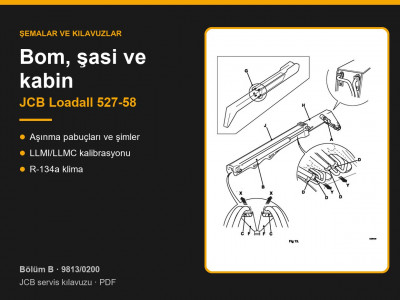
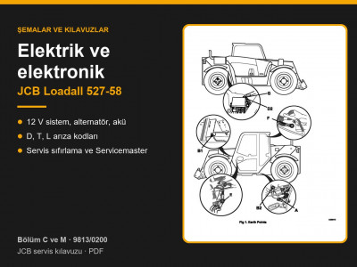
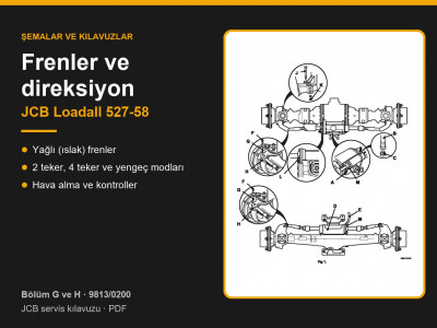
Other sections of the JCB Loadall 527-58 manual: routine maintenance, general data and torque settings, transmission and axles, brakes and steering, engine, electrics and electronics, boom, chassis and cab. To choose the right part, send us the machine model, the serial number and the JCB part number if you have it.
Parts enquiries