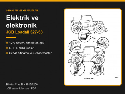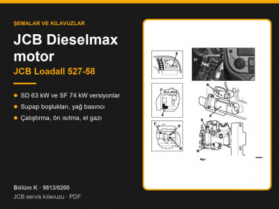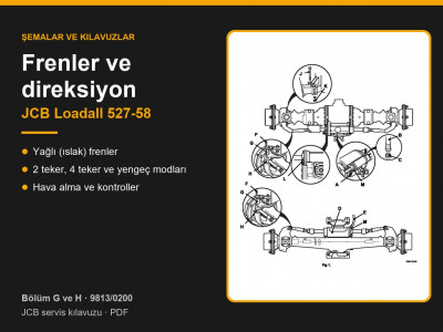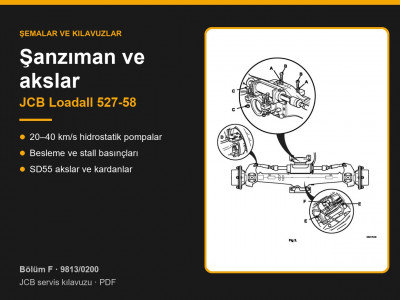
Service manual JCB 9813/0200 was written for the compact Loadall 527-58 telehandler with hydrostatic transmission. The applicability table on page 1-2-1 shows two JCB Dieselmax engine options: the turbocharged SD at 63 kW (85 hp) and the turbocharged, charge-cooled SF at 74 kW (100 hp). The transmission comes in four maximum speed versions: 20, 25, 34 and 40 km/h.
Contents by page — JCB Loadall 527-58 Section B
| Pages | What is covered |
|---|---|
| B1-1 – B1-4 | Fork carriage |
| B2 – B3 | Heating, ventilation and air conditioning |
| B4-1 – B4-30 | Longitudinal load moment system LLMI/LLMC: operation, calibration, fault codes, tests |
| B5-1 – B5-18 | Cab: panels, door, wipers, removal |
| B6 – B9 | Condenser, pressure switch, HVAC unit, heater control valve |
| B10 – B11 | Fuel tank, chassis panels |
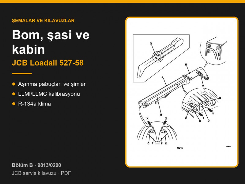
| B12-1 – B12-20 | Boom: wear pads and shims, angle indicator, removal, dismantling, hoses |
| B13-1 – B13-4 | Axle load sensor |
Boom wear pads
- Maximum clearance at A and B is 1.5 mm (page B12-3), checked every 500 hours. Renew the pads once they are worn down to the depth of the chamfer; partly worn pads can be shimmed.
- Shims are fitted between the inner and outer boom sections. Side shims are split equally between both sides so that the inner section stays central.
- Wear pad bolt torques: M12 — 98 Nm, M10 — 56 Nm (page B12-7).
- After assembling the boom, compare the carriage height on the left and right with the tyres at the correct pressure. If it differs, adjust the shims under the lower front pads; the difference in shim thickness between the sides must not exceed 3.2 mm (page B12-8).
- Total clearance along the boom axis must not exceed 3 mm, with shims fitted equally on both sides (page B12-10).
- The hoses inside the boom stretch in service, so they are never replaced one at a time: if one is damaged, all four are renewed, and the lengths in each pair must match within ±1 mm (page B12-14).
Load moment control LLMI/LLMC
A sensor on the rear axle measures the load, and the cab indicator shows the remaining stability margin with three green, an amber and a red LED; the red LED comes on together with an audible alarm. The system only monitors longitudinal tipping forwards. As the machine approaches the limit, LLMC first slows and then stops boom lower, boom extend and tilt, while boom raise and retract stay available. The cut-out can be overridden with a button for no longer than 60 seconds (pages B4-3 – B4-13).
- Calibration (page B4-14): a 2700 kg load, the boom no higher than 600 mm above the ground, and 5 minutes for the whole procedure. To enter calibration, hold the button for about 30 seconds while starting the machine. Extend the boom until the rear wheels lift and press the button, then remove the load, set the boom horizontal and press the button again.
- Calibration is mandatory after the axle sensor has been replaced. The sensor is fitted with retainer compound and its M12 bolt is torqued to 122 Nm (page B13-3).
- Test box check: ECU and sensor supply 11–15 V, axle sensor signal 4.3–4.7 V (page B4-24).
Air conditioning
| Parameter | Value |
|---|---|
| Refrigerant | R-134a, 1.7 kg |
| Oil | PAG; when recharging, add the same amount as was drained |
| Binary pressure switch | low pressure 2 bar, high pressure 26 bar |
| Pressures at 25 °C | low side 1.53 bar, high side 10.8 bar |
| Thermostat | cut-out 0.2–1.4 °C, cut-in 3.4–4.8 °C |
| Evacuation | 740 mm Hg, about 30 minutes |
Data taken from pages B3-3, B3-17, B3-26. Out of season, run the air conditioning at least once a month for a minimum of 5 minutes.
Cab parts and glass are listed under cab and glass, wear pads and boom parts under body parts, and hoses under hydraulic hoses.
Other sections of the JCB Loadall 527-58 manual: routine maintenance, general data and torque settings, hydraulics, transmission and axles, brakes and steering, engine, electrics and electronics. To choose a part, send us the machine model, serial number and the JCB part number if you know it.
Parts enquiries