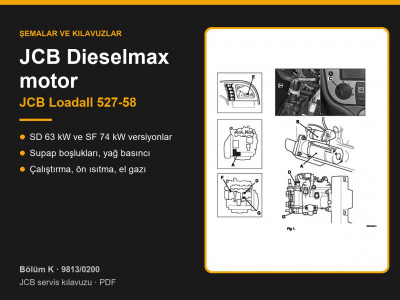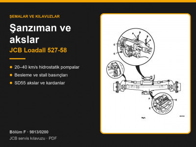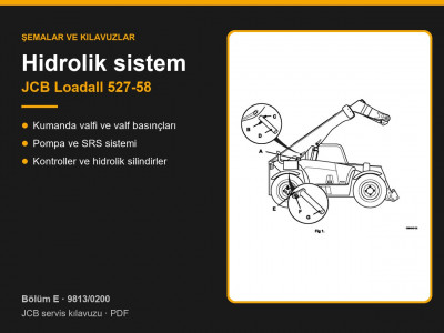
Service manual JCB 9813/0200 applies to the compact Loadall 527-58 telehandler with hydrostatic transmission. According to the applicability table (page 1-2-1), the machine was fitted with two versions of the JCB Dieselmax engine: the turbocharged SD rated at 63 kW (85 hp) and the turbocharged and charge-cooled SF rated at 74 kW (100 hp). The transmission was built in four maximum speed versions: 20, 25, 34 and 40 km/h.
Contents by page — JCB Loadall 527-58 electrics
| Pages | What is covered |
|---|---|
| C1-1 – C1-4 | Fuses and relays (with references to Section 3) |
| C2-1 – C2-30 | Wiring diagram and connector keys |
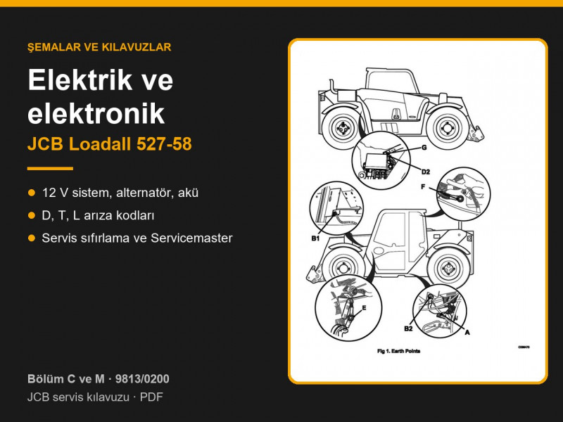
| C3-1 – C3-54 | Harnesses, earth points, wire numbering, repair |
| C4 – C6 | Charging, alternator, battery |
| M1 – M2 | CAN bus, Loadall Monitoring System (LMS), service hours reset |
| M3-1 – M3-50 | D, T and L fault codes |
| M4 – M5 | Servicemaster: installation, LMS setup, diagnostics |
| M6 – M7 | ECU and PWM theory |
Technical data
| Item | Data |
|---|---|
| Electrical system | 12 V, negative earth |
| Battery | 120 Ah, 1000 A cranking current |
| Alternator | 12 V, 95 A; no-load speed 1100 rev/min; renew the brushes when shorter than 8 mm |
| Alternator torque settings | mounting 47 Nm, B+ terminal 9–13 Nm, D+ and W terminals 2.7–3.8 Nm |
| Fuses | about 40 secondary fuses; main fuses 70, 50, 60 and 80 A; cold start heater 150 A |
Data taken from pages C4-3, C5-3, C5-6 and Section 3 (pages 3-1-52 – 3-1-54). The wiring diagram key lists these relays: neutral/start and ignition, stop lights, reverse and road lights, throttle actuator reverse, direction indicators, work lights and condenser fans.
Battery and charging
- Load test: the battery must be at least 75 % charged and show at least 12.4 V off load; under load for 5–10 seconds the voltage must not fall below 9 V (page C6-6).
- Electrolyte specific gravity at 15 °C: fully charged 1.270–1.290, half charged 1.190–1.210, discharged 1.110–1.130; the difference between cells must not exceed 0.04.
- Never charge a maintenance-free battery at more than 15.8 V.
- Charging output is checked with a 100 A shunt at maximum engine speed. If there is no output, the likely causes in order of probability are: capacitor, brushes and slip rings, regulator, rectifier, rotor, stator (page C4-7).
Fault codes
A red warning light with a continuous alarm means “STOP NOW”; an amber light with a 1-second alarm means “SERVICE”. The display log stores up to 30 entries (pages M3-3, M3-4). Some example codes:
| Code | Meaning |
|---|---|
| D001 | Air filter blocked |
| D002 / D003 | Water in fuel |
| D004 | Coolant overheating |
| D006 | Transmission oil overheating |
| D012 | Low engine oil pressure |
| D205 | No charge |
| T000 – T004 | Column-mounted forward/reverse switch |
| T011 – T034 | Pump, motor and low speed solenoids |
| T040 / T041 | Park brake |
| T077 – T082 | Speed sensor |
| L036 – L044 | Boom extend and retract solenoids |
| L124 | Boom movement with the joystick in neutral |
| L127 / L128 | Emergency stop |
Service hours reset from the display: hold the Info button for 20 seconds, select SRV RST and hold for 3 seconds (page M2-10). With Servicemaster you can read fault codes, view ECU input and output states, set the machine build in LMS Setup and reflash the ECUs. The diagnostic connector is a Deutsch 9-pin.
Alternators, starter motors and batteries are listed under alternators, starter motors and batteries; relays and sensors under relays and sensors.
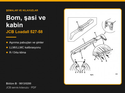
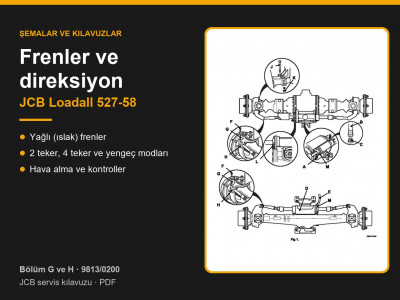
Other sections of the JCB Loadall 527-58 manual: routine maintenance, general data and torque settings, hydraulics, transmission and axles, brakes and steering, engine, boom, body and cab. To choose a part, send us the machine model, serial number and the JCB part number if you know it.
Parts enquiries