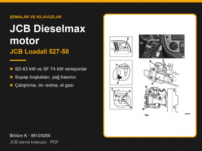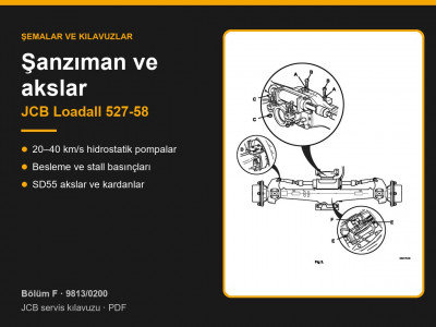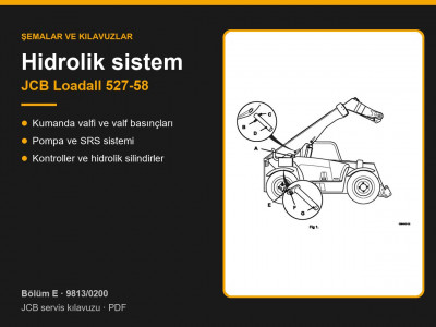

Service manual 9813/0200 covers the compact Loadall 527-58 telehandler with hydrostatic transmission. According to the applications table (page 1-2-1), the machine was built with two versions of the JCB Dieselmax engine – SD, 63 kW (85 hp), turbocharged, and SF, 74 kW (100 hp), turbocharged and charge-air cooled – and with the transmission in four maximum speed options: 20, 25, 34 and 40 km/h.
Contents by page – JCB Loadall 527-58 brakes and steering
| Pages | What the section covers |
|---|---|
| G1-1 – G2-12 | Non-boosted and boosted service brakes |
| G3-1 – G6 | Park brake: calliper, disc, switch |
| G7 – G9 | Master cylinder, fluid reservoir, brake manifold |
| H1-1 – H1-26 | Steering system: specifications, fault finding, tests, bleeding |
| H2 – H3 | Manual and auto steer mode selection |
| H4 – H9 | Hydraulic steering unit, priority valve, power track rod, steering column, steer mode valves |
Service brakes and park brake
- Non-boosted: single circuit with two oil-immersed brake packs in the centre of the front axle; master cylinder 25.4 mm, stroke 35 mm (page G1-3).
- Boosted: supplied from the transmission, with a brake manifold and accumulator; master cylinder 31.75 mm, boost ratio 2.6 : 1 (page G2-3). Before removing the manifold, press the pedal at least 6 times to release the stored pressure.
- The brake pedal both sends a signal to the transmission ECU and hydraulically reduces the displacement of the hydrostatic pump, so the machine brakes with reduced tractive effort.
- Park brake: 270 mm disc, minimum pad thickness 3.18 mm, minimum disc thickness 8.89 mm (page G3-3). Apply it on the move only in an emergency, and renew both pads afterwards. Calliper torque settings are 125 and 311 Nm.
- Brake fluid is JCB Hydraulic Fluid HP15; automotive brake fluid must not be used (Section 3).
Bleeding (page G1-11): give the pedal one fast full stroke followed by three fast short strokes from mid-travel, and close the bleed screw with the pedal held down. Bleed at the transmission pump first, then at the front axle, then at the trailer brake valve if one is fitted. The boosted system is bled with the engine running. For service brake disc wear limits the manual refers to the transmissions manual 9803/8610.
Steering
| Item | Value |
|---|---|
| Hydraulic steering unit | load sensing, 160 cm³/rev, integral relief and shock valves |
| Relief valve | 190 bar at 1500 rev/min |
| Shock valves | 250 bar |
| Priority valve standby pressure | 16–17 bar |
- Steer modes (page H2-3): in 2WS only the front wheels steer, in 4WS both axles steer for a tighter turning circle, and in crab mode the machine travels diagonally.
- In auto mode the steer mode cannot change until the wheels are straight ahead. The valve spools have mechanical detents, so the selected mode stays the same if electrical power is lost.
- Straight-ahead sensors: dimension X = 129 mm measured on the steering ram rod, sensor-to-disc gap 3 mm, locknuts 25 Nm (page H2-16).
- Wheel alignment after renewing the track rods: no more than 1 mm difference measured at the hub edge; track rod ends torqued to 240–260 Nm (page H6-6).
- Re-phase the wheels at least once a day, whenever steering becomes difficult and after 24 km of road travel in 2WS (Section 3).
Tests: connect a 0–70 bar gauge through a T-piece at port P of the steering unit. Standby pressure is read with the steering in neutral, and the pressure on lock at 1500 rev/min with the steering held against the stop (page H1-19). If the wheels drift out of phase, needing to re-phase after 4 hours of continuous work is considered normal; change steer modes at low engine speed with a 5-second pause.
Brake parts are listed under brake discs and brake cylinders, track rods and track rod ends under front axle, and steer mode solenoids under solenoids and valves.
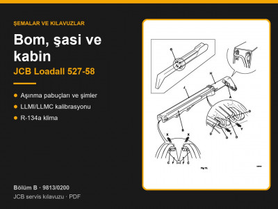
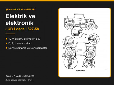
Other sections of the JCB Loadall 527-58 manual: routine maintenance, general data and torque settings, hydraulics, transmission and axles, engine, electrics and electronics, boom, mainframe and cab. To choose a part, send us the machine model, serial number and the JCB part number if you know it.
Parts enquiries